Installing a Brocade NetIron XMR 8000 router | 4 |
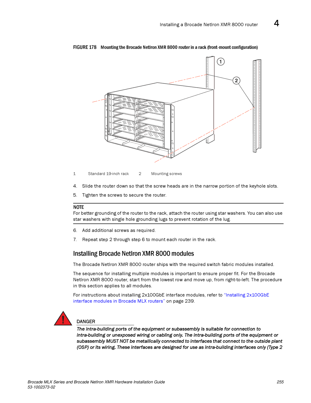
FIGURE 178 Mounting the Brocade NetIron XMR 8000 router in a rack (front-mount configuration)
1
2
1 | Standard | 2 | Mounting screws |
4.Slide the router down so that the screw heads are in the narrow portion of the keyhole slots.
5.Tighten the screws to secure the router.
NOTE
For better grounding of the router to the rack, attach the router using star washers. You can also use star washers with single hole grounding lugs to prevent rotation of the lug.
6.Add additional screws as required.
7.Repeat step 2 through step 6 to mount each router in the rack.
Installing Brocade NetIron XMR 8000 modules
The Brocade NetIron XMR 8000 router ships with the required switch fabric modules installed.
The sequence for installing multiple modules is important to ensure proper fit. For the Brocade NetIron XMR 8000 router, start from the lowest row and move up, from
For instructions about installing 2x100GbE interface modules, refer to “Installing 2x100GbE interface modules in Brocade MLX routers” on page 239.
DANGER
The
Brocade MLX Series and Brocade NetIron XMR Hardware Installation Guide | 255 |
|
|