Installing a Brocade | 2 |
You can install up to six Brocade
Front- or mid-mount your device in a standard rack
Your Brocade
You will need to provide four standard
If you are installing your Brocade
NOTE
When connecting the device to the rack frame, use
Follow these steps to mount your device in a standard
1.Determine the position of each router in the rack according to weight. For example, mount the router with the fewest modules near the top of the rack, the router with more modules near the middle of the rack, and a fully populated router near the bottom of the rack.
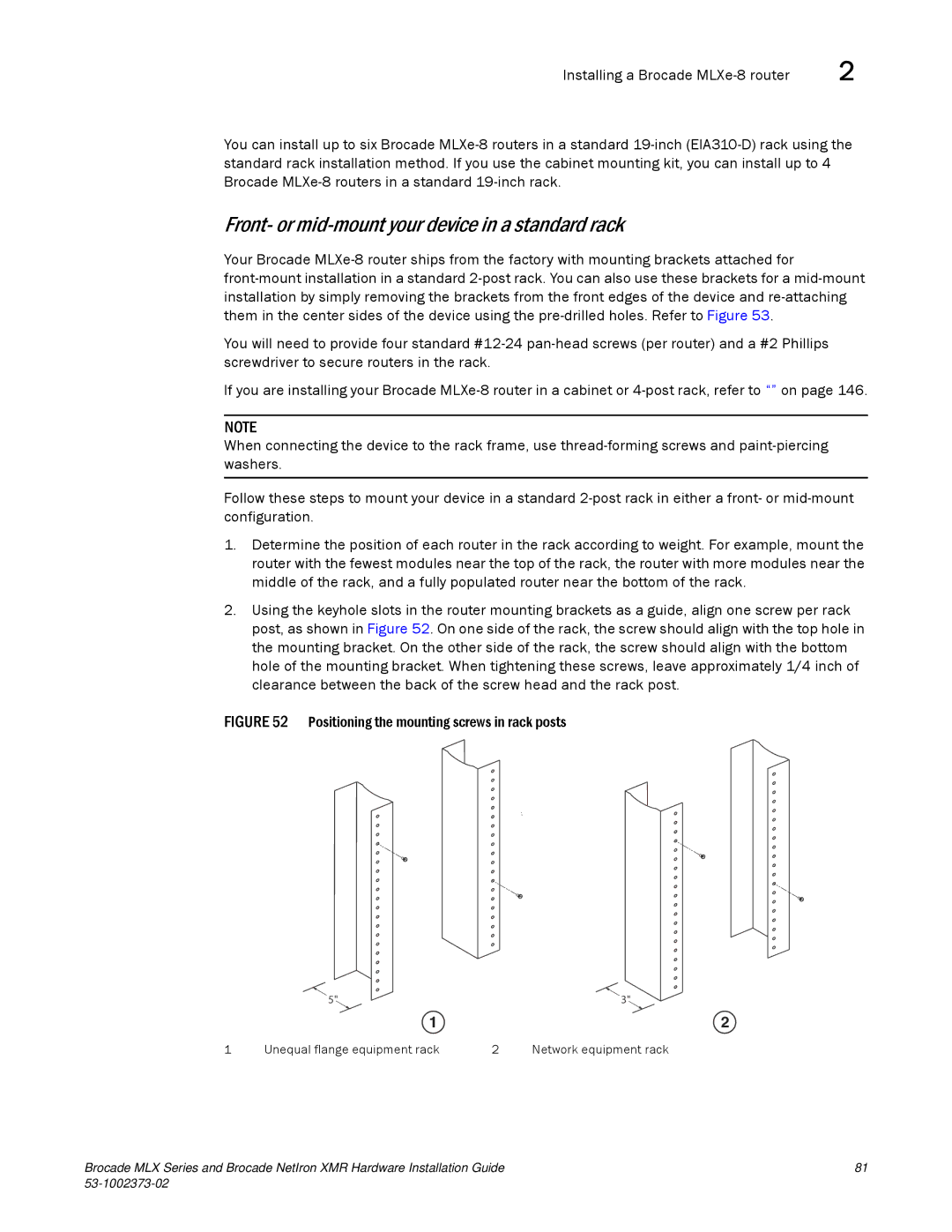
2.Using the keyhole slots in the router mounting brackets as a guide, align one screw per rack post, as shown in Figure 52. On one side of the rack, the screw should align with the top hole in the mounting bracket. On the other side of the rack, the screw should align with the bottom hole of the mounting bracket. When tightening these screws, leave approximately 1/4 inch of clearance between the back of the screw head and the rack post.
FIGURE 52 Positioning the mounting screws in rack posts
| 5" |
| 3" |
| 1 |
| 2 |
1 | Unequal flange equipment rack | 2 | Network equipment rack |
Brocade MLX Series and Brocade NetIron XMR Hardware Installation Guide | 81 |
|
|