3 Installing a Brocade
•During the initial installation of modules, it is recommended that you insert all the modules into the appropriate router slots before tightening the module screws.
For instructions about installing 100xGbE interface modules, refer to “Installing 2x100GbE interface modules in Brocade MLX routers” on page 151.
For information about how to disable and
When populating the Brocade
•Management modules - management slots 1 and 2
•Switch fabric modules - switch fabric slots
•Interface modules - interface slots
Figure 12 on page 16 shows the locations of these slots.
Using the insertion and extraction tool
Due to the high density of cables that the Brocade
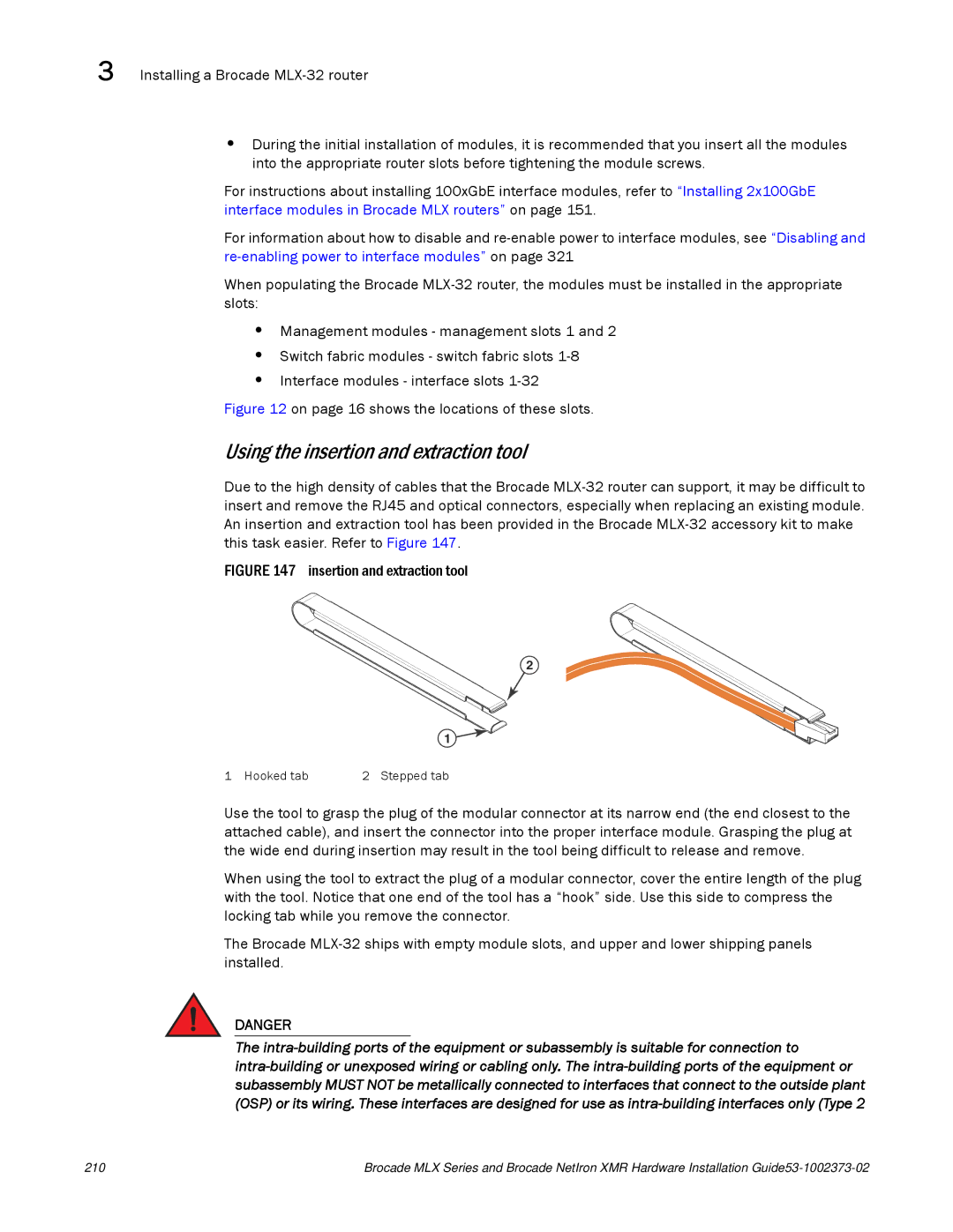
FIGURE 147 insertion and extraction tool
2
1
1 Hooked tab | 2 Stepped tab |
Use the tool to grasp the plug of the modular connector at its narrow end (the end closest to the attached cable), and insert the connector into the proper interface module. Grasping the plug at the wide end during insertion may result in the tool being difficult to release and remove.
When using the tool to extract the plug of a modular connector, cover the entire length of the plug with the tool. Notice that one end of the tool has a “hook” side. Use this side to compress the locking tab while you remove the connector.
The Brocade
DANGER
The
210 | Brocade MLX Series and Brocade NetIron XMR Hardware Installation |