1 Router modules
Gen-2 4-port 10 Gbps Ethernet interface modules
•
•
NOTE
The
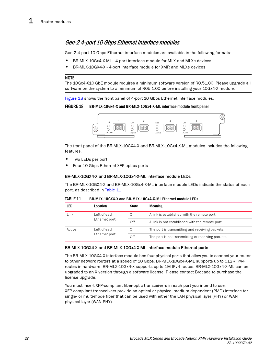
Figure 18 shows the front panel of 4-port 10 Gbps Ethernet interface modules.
FIGURE 18 BR-MLX-10Gx4-X and BR-MLX-10Gx4-X-ML interface module front panel
Lnk
1
Lnk
2
3
Lnk
Lnk
4
Active
Active
Active
Active
The front panel of the
•Two LEDs per port
•Four 10 Gbps Ethernet XFP optics ports
BR-MLX-10GX4-X and BR-MLX-10Gx4-X-ML interface module LEDs
The
TABLE 11
LED | Location | State | Meaning |
|
|
|
|
Link | Left of each | On | A link is established with the remote port. |
| Ethernet port |
|
|
| Off | A link is not established with the remote port. | |
|
| ||
|
|
|
|
Active | Left of each | On | The port is transmitting and receiving packets. |
| Ethernet port |
|
|
| Off | The port is not transmitting or receiving packets. | |
|
| ||
|
|
|
|
The
You must insert
32 | Brocade MLX Series and Brocade NetIron XMR Hardware Installation Guide |
|
