3 Installing 2x100GbE interface modules in Brocade MLX routers
DANGER
For safety reasons, the ESD wrist strap should contain a 1 megohm series resistor.
1.Upgrade the software on all management modules and interface modules to
2.Before you install your 2x100G interface module into a working device, you must change the system tm credit size to 1024b (which readies the device to forward 100 Gbps traffic). Log into your system and enter the following commands in the configuration level of the CLI. Remember to write to memory and reload the device.
Brocade# config
Brocade(config)#
Brocade(config)# exit
Brocade# write memory
Brocade# reload
NOTE
The
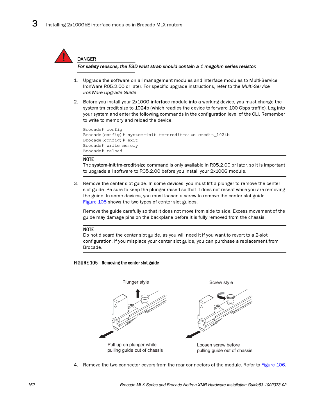
3.Remove the center slot guide. In some devices, you must lift a plunger to remove the center slot guide. Be sure to keep the plunger raised so that it does not reseat while you are removing the guide. In some devices, you must loosen a screw to remove the center slot guide.
Figure 105 shows the two types of center slot guides.
Remove the guide carefully so that it does not move from side to side. Excess movement of the guide may damage pins on the backplane before it is fully removed from the chassis.
NOTE
Do not discard the center slot guide, as you will need it if you want to revert to a 2-slot configuration. If you misplace your center slot guide, you can purchase a replacement from Brocade.
FIGURE 105 Removing the center slot guide
Plunger style | Screw style |
Pull up on plunger while | Loosen screw before |
pulling guide out of chassis | pulling guide out of chassis |
4. Remove the two connector covers from the rear connectors of the module. Refer to Figure 106.
152 | Brocade MLX Series and Brocade NetIron XMR Hardware Installation |