Managing the device | 7 |
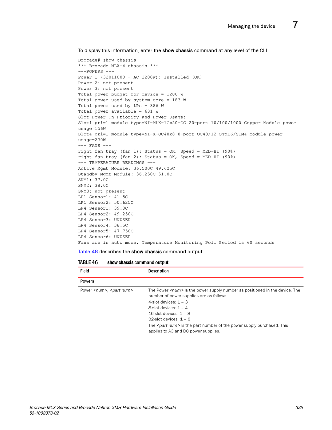
To display this information, enter the show chassis command at any level of the CLI.
Brocade# show chassis
*** Brocade
Power 1 (32011000 - AC 1200W): Installed (OK)
Power 2: not present
Power 3: not present
Total power budget for device = 1200 W Total power used by system core = 183 W Total power used by LPs = 386 W
Total power available = 631 W
Slot
Slot1 pri=1 module
Slot4 pri=1 module
right fan tray (fan 1): Status = OK, Speed =
right fan tray (fan 2): Status = OK, Speed =
--- TEMPERATURE READINGS ---
Active Mgmt Module: 36.500C 49.625C
Standby Mgmt Module: 36.250C 51.0C
SNM1: 37.0C
SNM2: 38.0C
SNM3: not present
LP1 Sensor1: 41.5C
LP1 Sensor2: 50.625C
LP4 Sensor1: 39.0C
LP4 Sensor2: 49.250C
LP4 Sensor3: UNUSED
LP4 Sensor4: 38.5C
LP4 Sensor5: 47.750C
LP4 Sensor6: UNUSED
Fans are in auto mode. Temperature Monitoring Poll Period is 60 seconds Table 46 describes the show chassis command output.
TABLE 46 | show chassis command output |
|
|
Field | Description |
Powers
Power <num>, <part num> The Power <num> is the power supply number as positioned in the device. The number of power supplies are as follows:
The <part num> is the part number of the power supply purchased. This applies to AC and DC power supplies.
Brocade MLX Series and Brocade NetIron XMR Hardware Installation Guide | 325 |
|
|
