Router modules | 1 |
Before you install a 2x100GbE module, you will need to remove the center slot guide that divides the slot into two partitions. Do not discard this guide, as you will need it if you ever want to convert the slot into two slots. For information about how to remove the center guide and install
NOTE
Before installing the 100GbE module in a chassis, the
You will also need to change the system tm credit size to 1024b (which readies the device to forward 100 Gbps traffic). Log into your system and enter the following commands in the configuration level of the CLI. Remember to write to memory and reload the device.
Brocade# config
Brocade(config)#
Brocade(config)# exit
Brocade# write memory
Brocade# reload
NOTE
The 100GbE module requires a minimum software version of R05.2.00. Please upgrade all software on the system to a minimum version of R05.2.00 before you inst all your 2x100G module.
NOTE
100xGbE modules require
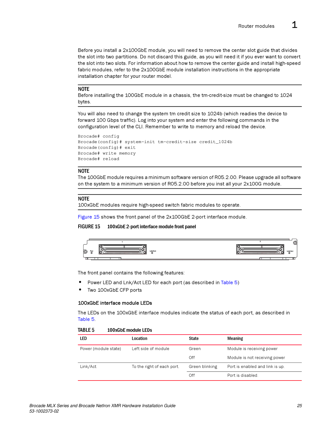
Figure 15 shows the front panel of the 2x100GbE 2-port interface module.
FIGURE 15 100xGbE 2-port interface module front panel
Pwr
1
Lnk/Act |
2
Lnk/Act |
The front panel contains the following features:
•Power LED and Lnk/Act LED for each port (as described in Table 5)
•Two 100xGbE CFP ports
100xGbE interface module LEDs
The LEDs on the 100xGbE interface modules indicate the status of each port, as described in Table 5.
TABLE 5 | 100xGbE module LEDs |
|
| |
|
|
|
|
|
LED |
| Location | State | Meaning |
|
|
|
| |
Power (module state) | Left side of module | Green | Module is receiving power | |
|
|
| Off | Module is not receiving power |
|
|
|
|
|
Link/Act |
| To the right of each port. | Green blinking | Port is enabled and link is up. |
|
|
|
|
|
|
|
| Off | Port is disabled. |
|
|
|
|
|
Brocade MLX Series and Brocade NetIron XMR Hardware Installation Guide | 25 |
|