2 Installing a Brocade MLXe-32 router
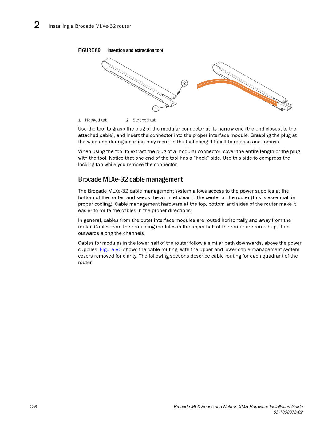
FIGURE 89 insertion and extraction tool
2
1
1 Hooked tab | 2 Stepped tab |
Use the tool to grasp the plug of the modular connector at its narrow end (the end closest to the attached cable), and insert the connector into the proper interface module. Grasping the plug at the wide end during insertion may result in the tool being difficult to release and remove.
When using the tool to extract the plug of a modular connector, cover the entire length of the plug with the tool. Notice that one end of the tool has a “hook” side. Use this side to compress the locking tab while you remove the connector.
Brocade MLXe-32 cable management
The Brocade
In general, cables from the outer interface modules are routed horizontally and away from the router. Cables from the remaining modules in the upper half of the router are routed up, then outwards along the channels.
Cables for modules in the lower half of the router follow a similar path downwards, above the power supplies. Figure 90 shows the cable routing, with the upper and lower cable management system covers removed for clarity. The following sections describe cable routing for each quadrant of the router.
126 | Brocade MLX Series and NetIron XMR Hardware Installation Guide |
|
|