Router modules | 1 |
The front panel includes the following features:
•LEDs to the left support the top ports, LEDs to the right support the bottom ports
•20 100/1000 Ethernet SFP ports
Table 19 describes the LEDs for the
TABLE 19 |
| |||
|
|
|
| |
Position |
| State | Meaning | |
|
|
| ||
Below each Ethernet port. | On or blinking | The port is transmitting and receiving packets. | ||
|
| |||
Off for an extended period | The port is not transmitting or receiving packets. | |||
top row. | ||||
|
| |||
port in bottom row.)
100/1000 Ethernet ports
The 100/1000 Ethernet interface module contains 20 physical ports, through which you can connect your router to other network routers at a speed of 100 Mbps or 1 Gbps.
You must insert an
For a list of SFP optics supported by Brocade, refer to the latest version of the Brocade Optics Family Data Sheet, available online in the following location:
http://www.brocade.com/downloads/documents/data_sheets/product_data_sheets/Optics_DS.p df
20-port 10/100/1000 Ethernet interface module
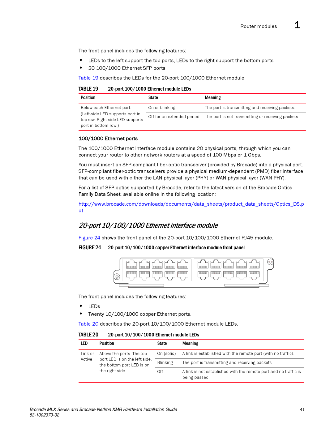
Figure 24 shows the front panel of the 20-port 10/100/1000 Ethernet RJ45 module.
FIGURE 24 20-port 10/100/1000 copper Ethernet interface module front panel
The front panel includes the following features:
•LEDs
•Twenty 10/100/1000 copper Ethernet ports.
Table 20 describes the 20-port 10/100/1000 Ethernet module LEDs.
TABLE 20 |
| |||
|
|
|
| |
LED | Position | State | Meaning | |
|
|
|
| |
Link or | Above the ports. The top | On (solid) | A link is established with the remote port (with no traffic). | |
Active | port LED is on the left side, |
|
| |
Blinking | The port is transmitting and receiving packets. | |||
| the bottom port LED is on | |||
|
|
| ||
| the right side. | Off | A link is not established with the remote port and no traffic is | |
|
|
| being passed. | |
|
|
|
| |
Brocade MLX Series and Brocade NetIron XMR Hardware Installation Guide | 41 |
|