4 Installing a Brocade NetIron XMR 32000 router
Using the insertion or extraction tool
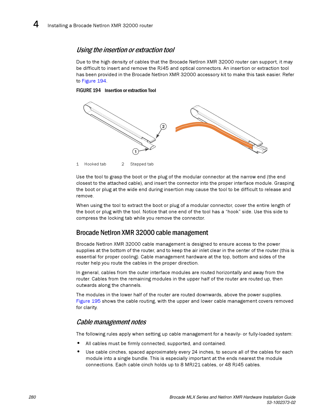
Due to the high density of cables that the Brocade NetIron XMR 32000 router can support, it may be difficult to insert and remove the RJ45 and optical connectors. An insertion or extraction tool has been provided in the Brocade NetIron XMR 32000 accessory kit to make this task easier. Refer to Figure 194.
FIGURE 194 Insertion or extraction Tool
2
1
1 Hooked tab | 2 Stepped tab |
Use the tool to grasp the boot or the plug of the modular connector at the narrow end (the end closest to the attached cable), and insert the connector into the proper interface module. Grasping the boot or plug at the wide end during insertion may cause the tool to be difficult to release and remove.
When using the tool to extract the boot or plug of a modular connector, cover the entire length of the boot or plug with the tool. Notice that one end of the tool has a “hook” side. Use this side to compress the locking tab while you remove the connector.
Brocade NetIron XMR 32000 cable management
Brocade NetIron XMR 32000 cable management is designed to ensure access to the power supplies at the bottom of the router, and to keep the air inlet clear in the center of the router (this is essential for proper cooling). Cable management hardware at the top, bottom and sides of the router help you route the cables in the proper direction.
In general, cables from the outer interface modules are routed horizontally and away from the router. Cables from the remaining modules in the upper half of the router are routed up, then outwards along the channels.
The modules in the lower half of the router are routed downwards, above the power supplies. Figure 195 shows the cable routing, with the upper and lower cable management covers removed for clarity.
Cable management notes
The following rules apply when setting up cable management for a heavily- or
•All cables must be firmly connected, supported, and contained.
•Use cable cinches, spaced approximately every 24 inches, to secure all of the cables for each module into a single bundle. This is especially important at the ends nearest the module connections. Each cable cinch holds up to 8 MRJ21 cables, or 48 RJ45 cables.
280 | Brocade MLX Series and NetIron XMR Hardware Installation Guide |
|
|