3 Installing a Brocade
allowing it to be connected to both ground screws on the enclosure. Before crimping the ground wire into the provided ground lug, ensure the bare copper wire has been cleaned and antioxidant is applied to the bare wire.
CAUTION
To ensure adequate bonding when attaching the ground lug, a minimum of 20 PSI of torque is required to be applied to the mounting hardware used to attach the ground lug.
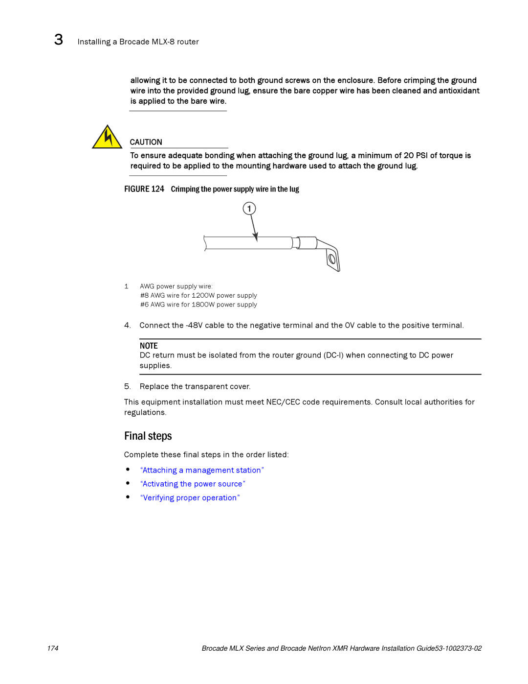
FIGURE 124 Crimping the power supply wire in the lug
1
1AWG power supply wire:
#8 AWG wire for 1200W power supply #6 AWG wire for 1800W power supply
4.Connect the
NOTE
DC return must be isolated from the router ground
5.Replace the transparent cover.
This equipment installation must meet NEC/CEC code requirements. Consult local authorities for regulations.
Final steps
Complete these final steps in the order listed:
•“Attaching a management station”
•“Activating the power source”
•“Verifying proper operation”
174 | Brocade MLX Series and Brocade NetIron XMR Hardware Installation |