Installing 2x100GbE interface modules in Brocade MLXe routers | 2 |
FIGURE 42 Removing the center slot guide
Plunger style | Screw style |
Pull up on plunger while | Loosen screw before |
pulling guide out of chassis | pulling guide out of chassis |
4.Remove the two connector covers from the rear connectors of the module. Refer to Figure 43.
5.Remove the port cover from one or both ports, depending on how you plan to use your module. If you are using one port only (always Port 1), you must leave the port cover in the inactive port (always Port 2). Port covers are designed for a tight fit and will take some effort to remove.
Refer to Figure 43.
NOTE
Do not use the port cover tabs to lift the module. They are not designed to support the weight of the module, which can fall and be damaged.
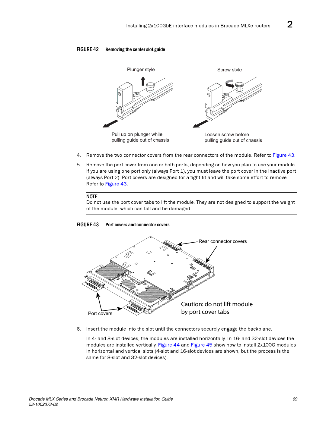
FIGURE 43 Port covers and connector covers
Rear connector covers
Port covers
Caution: do not lift module by port cover tabs
6.Insert the module into the slot until the connectors securely engage the backplane.
In 4- and
Brocade MLX Series and Brocade NetIron XMR Hardware Installation Guide | 69 |
|