Router modules | 1 |
Gen-1 10Gx2 and 10Gx4 Ethernet interface modules
•
•
•
•
NOTE
When you install
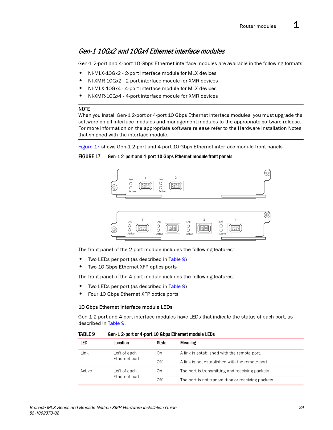
Figure 17 shows Gen-1 2-port and 4-port 10 Gbps Ethernet interface module front panels.
FIGURE 17 Gen-1 2-port and 4-port 10 Gbps Ethernet module front panels
Lnk | 1 | Lnk | 2 |
|
| ||
Active |
| Active |
|
Lnk | 1 | 2 | 3 | |||||||||
|
| Lnk |
|
| Lnk | |||||||
|
|
|
|
|
|
|
|
|
|
|
|
|
|
|
|
|
|
|
|
|
|
|
|
|
|
Lnk
4
| Active |
| Active |
| Active | ||
|
|
| |||||
|
|
|
|
|
|
|
|
Active
The front panel of the
•Two LEDs per port (as described in Table 9)
•Two 10 Gbps Ethernet XFP optics ports
The front panel of the
•Two LEDs per port (as described in Table 9)
•Four 10 Gbps Ethernet XFP optics ports
10 Gbps Ethernet interface module LEDs
TABLE 9 | |||
|
|
|
|
LED | Location | State | Meaning |
|
|
|
|
Link | Left of each | On | A link is established with the remote port. |
| Ethernet port |
|
|
| Off | A link is not established with the remote port. | |
|
| ||
|
|
|
|
Active | Left of each | On | The port is transmitting and receiving packets. |
| Ethernet port |
|
|
| Off | The port is not transmitting or receiving packets. | |
|
| ||
|
|
|
|
Brocade MLX Series and Brocade NetIron XMR Hardware Installation Guide | 29 |
|