Installing 2x100GbE interface modules in Brocade MLX routers | 3 |
5.Remove the port cover from one or both ports, depending on how you plan to use your module. If you are using one port only (always Port 1), you must leave the port cover in the inactive port (always Port 2). Port covers are designed for a tight fit and will take some effort to remove.
Refer to Figure 106.
NOTE
Do not use the port cover tabs to lift the module. They are not designed to support the weight of the module, which can fall and be damaged.
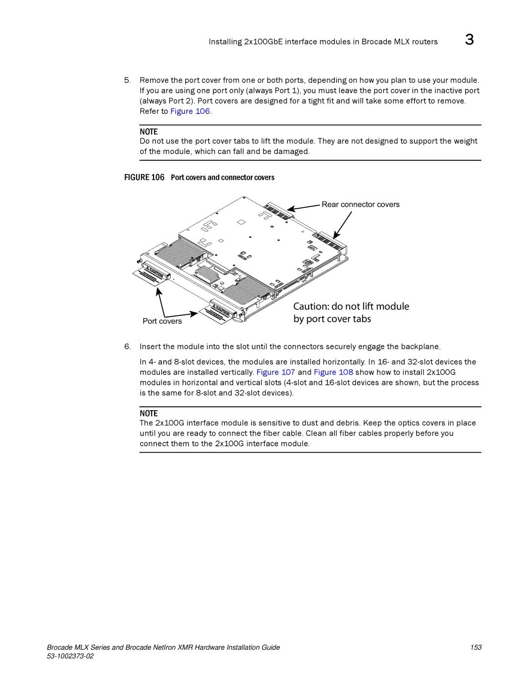
FIGURE 106 Port covers and connector covers
Rear connector covers
Port covers
Caution: do not lift module by port cover tabs
6.Insert the module into the slot until the connectors securely engage the backplane.
In 4- and
NOTE
The 2x100G interface module is sensitive to dust and debris. Keep the optics covers in place until you are ready to connect the fiber cable. Clean all fiber cables properly before you connect them to the 2x100G interface module.
Brocade MLX Series and Brocade NetIron XMR Hardware Installation Guide | 153 |
|
|