1 Router modules
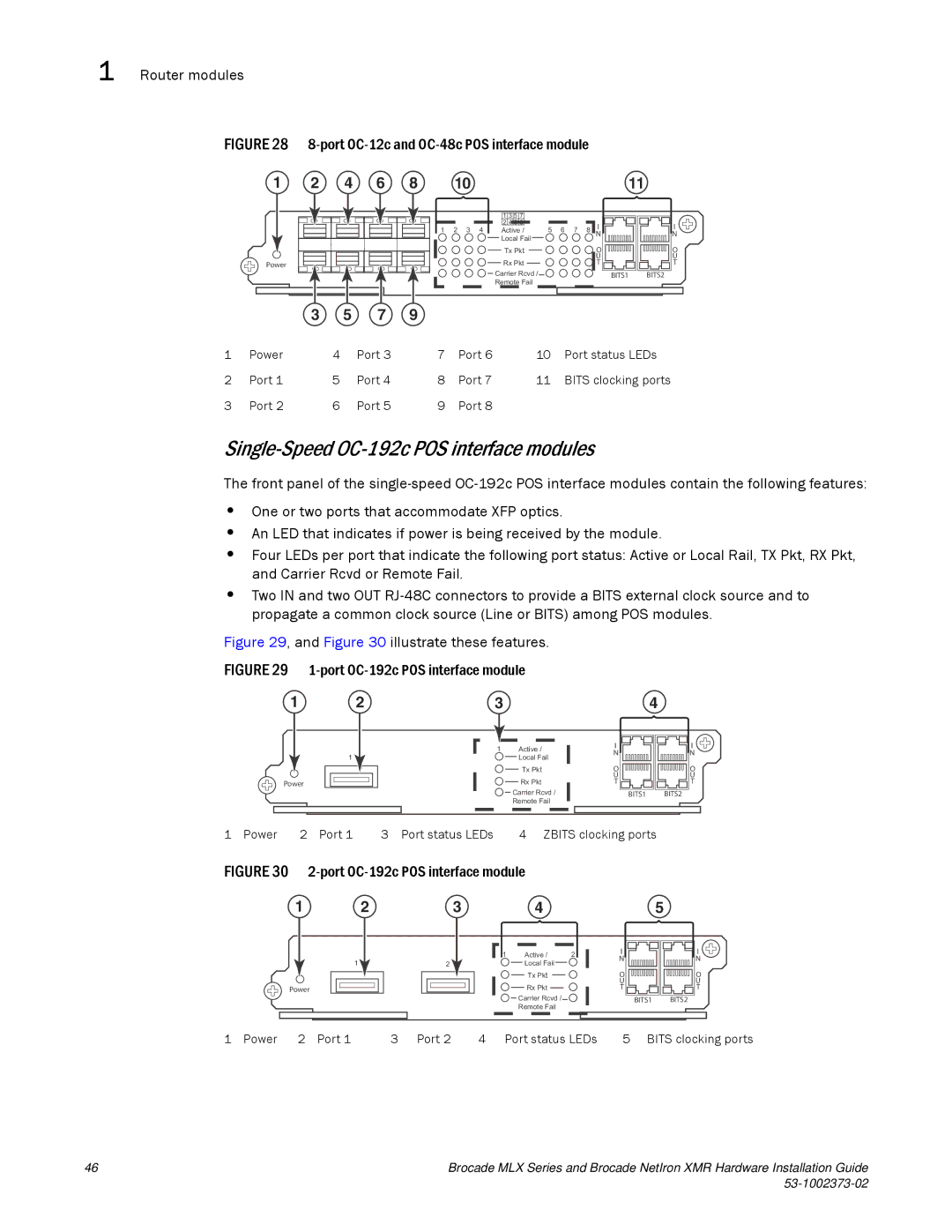
FIGURE 28 8-port OC-12c and OC-48c POS interface module
1 | 2 | 4 | 6 | 8 | 10 |
|
|
|
|
|
|
|
|
|
|
|
|
|
| 1 3 5 7 |
|
|
|
|
|
|
|
|
| 1 | 2 3 | 4 | 2 4 6 8 | 5 | 6 | 7 | 8 | I |
|
|
|
| Active / | ||||||||
|
|
|
|
|
|
| Local Fail |
|
|
|
| N |
|
|
|
|
|
|
|
|
|
|
|
| |
|
|
|
|
|
|
| Tx Pkt |
|
|
|
| O |
|
|
|
|
|
|
|
|
|
|
|
| U |
Power |
|
|
|
|
|
| Rx Pkt |
|
|
|
| T |
|
|
|
|
|
|
| Carrier Rcvd / |
|
|
|
|
|
|
|
|
|
|
|
| Remote Fail |
|
|
|
|
|
| 3 | 5 | 7 | 9 |
|
|
|
|
|
|
|
|
11
I
N
O
U
T
BITS1 BITS2
1 | Power | 4 | Port 3 | 7 | Port 6 | 10 | Port status LEDs |
2 | Port 1 | 5 | Port 4 | 8 | Port 7 | 11 | BITS clocking ports |
3 | Port 2 | 6 | Port 5 | 9 | Port 8 |
|
|
Single-Speed OC-192c POS interface modules
The front panel of the
•One or two ports that accommodate XFP optics.
•An LED that indicates if power is being received by the module.
•Four LEDs per port that indicate the following port status: Active or Local Rail, TX Pkt, RX Pkt, and Carrier Rcvd or Remote Fail.
•Two IN and two OUT
Figure 29, and Figure 30 illustrate these features.
FIGURE 29 1-port OC-192c POS interface module
1 | 2 | 3 |
|
| 1 | 1 | Active / |
|
| Local Fail | |
|
|
| Tx Pkt |
Power |
|
| Rx Pkt |
![]()
![]() Carrier Rcvd /
Carrier Rcvd /
Remote Fail
|
|
|
|
|
|
|
|
|
|
|
|
|
|
|
|
|
| 4 |
|
|
|
|
|
|
|
|
|
|
|
|
|
|
|
|
|
|
|
|
|
|
| ||
| I |
|
|
|
|
|
|
|
|
|
|
|
|
|
|
|
|
|
|
|
|
|
|
|
|
| I | ||||||||||||||||
|
|
|
|
|
|
|
|
|
|
|
|
|
|
|
|
|
|
|
|
|
|
|
|
|
| ||||||||||||||||||
| N |
|
|
|
|
|
|
|
|
|
|
|
|
|
|
|
|
|
|
|
|
|
|
|
|
|
|
|
|
|
|
|
|
|
|
|
|
|
|
|
| N | |
| O |
|
|
|
|
|
|
|
|
|
|
|
|
|
|
|
|
|
|
|
|
|
|
|
|
| O | ||||||||||||||||
|
|
|
|
|
|
|
|
|
|
|
|
|
|
|
|
|
|
|
|
|
|
|
|
|
|
|
|
|
|
|
|
|
|
|
|
|
|
|
|
| |||
| U |
|
|
|
|
|
|
|
|
|
|
|
|
|
|
|
|
|
|
|
|
|
|
|
|
| U | ||||||||||||||||
| T |
|
|
|
|
|
|
|
|
|
|
|
|
|
|
|
|
|
|
|
|
|
|
|
|
| T | ||||||||||||||||
|
|
|
| BITS1 |
|
|
| BITS2 | |||||||||||||||||||||||||||||||||||
|
|
|
|
|
|
|
|
|
|
|
|
|
|
|
|
|
|
|
|
|
|
|
|
|
|
|
|
|
|
|
|
|
|
|
|
|
|
|
|
|
|
|
|
1 Power 2 Port 1 | 3 Port status LEDs | 4 ZBITS clocking ports |
FIGURE 30 2-port OC-192c POS interface module
12
1
Power
3 | 4 |
|
| |
1 | Active / | 2 | I | |
N | ||||
2 | Local Fail |
| ||
|
| |||
| Tx Pkt |
| O | |
| Rx Pkt |
| U | |
|
| T |
![]()
![]() Carrier Rcvd /
Carrier Rcvd /![]()
![]()
Remote Fail
5
I
N
O
U
T
BITS1 BITS2
1 Power 2 Port 1 | 3 Port 2 | 4 Port status LEDs | 5 BITS clocking ports |
46 | Brocade MLX Series and Brocade NetIron XMR Hardware Installation Guide |
|