Verifying proper operation | 4 |
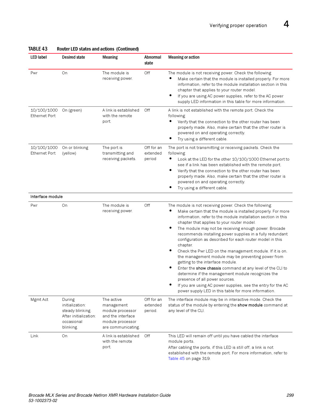
TABLE 43 Router LED states and actions (Continued)
LED label | Desired state | Meaning | Abnormal | Meaning or action |
|
|
| state |
|
|
|
|
|
|
Pwr | On | The module is | Off | The module is not receiving power. Check the following: |
|
| receiving power. |
| • Make certain that the module is installed properly. For more |
|
|
|
| information, refer to the module installation section in this |
|
|
|
| chapter that applies to your router model. |
|
|
|
| • If you are using AC power supplies, refer to the AC power |
|
|
|
| supply LED information in this table for more information. |
|
|
|
|
|
10/100/1000 | On (green) | A link is established | Off | A link is not established with the remote port. Check the |
Ethernet Port |
| with the remote |
| following: |
|
| port. |
| • Verify that the connection to the other router has been |
|
|
|
| properly made. Also, make certain that the other router is |
|
|
|
| powered on and operating correctly. |
|
|
|
| • Try using a different cable. |
|
|
|
|
|
10/100/1000 | On or blinking | The port is | Off for an | The port is not transmitting or receiving packets. Check the |
Ethernet Port | (yellow) | transmitting and | extended | following: |
|
| receiving packets. | period | • Look at the LED for the other 10/100/1000 Ethernet port to |
|
|
|
| see if a link has been established with the remote port. |
|
|
|
| • Verify that the connection to the other router has been |
|
|
|
| properly made. Also, make certain that the other router is |
|
|
|
| powered on and operating correctly. |
|
|
|
| • Try using a different cable. |
|
|
|
| |
Interface module |
|
|
| |
|
|
|
|
|
Pwr | On | The module is | Off | The module is not receiving power. Check the following: |
|
| receiving power. |
| • Make certain that the module is installed properly. For more |
|
|
|
| information, refer to the module installation section in this |
|
|
|
| chapter that applies to your router model. |
|
|
|
| • The module may not be receiving enough power. Brocade |
|
|
|
| recommends installing power supplies in a fully redundant |
|
|
|
| configuration as described for each router model in this |
|
|
|
| chapter. |
|
|
|
| • Check the Pwr LED on the management module. If it is on, |
|
|
|
| the management module may be preventing power from |
|
|
|
| getting to the interface module. |
|
|
|
| • Enter the show chassis command at any level of the CLI to |
|
|
|
| determine if the management module recognizes the |
|
|
|
| presence of all power sources. |
|
|
|
| • If you are using AC power supplies, see the entry for the AC |
|
|
|
| power supply LED in this table for more information. |
|
|
|
|
|
Mgmt Act | During | The active | Off for an | The interface module may be in interactive mode. Check the |
| initialization: | management | extended | status of the module by entering the show module command at |
| steady blinking. | module processor | period. | any level of the CLI. |
| After initialization: | and the interface |
|
|
| occasional | module processor |
|
|
| blinking. | are communicating. |
|
|
|
|
|
|
|
Link | On | A link is established | Off | This LED will remain off until you have cabled the interface |
|
| with the remote |
| module ports. |
|
| port. |
| After cabling the ports, if this LED is still off, a link is not |
|
|
|
| established with the remote port. For more information, refer to |
|
|
|
| Table 45 on page 319. |
Brocade MLX Series and Brocade NetIron XMR Hardware Installation Guide | 299 |
|
|
