7 | Managing the device |
|
| |
|
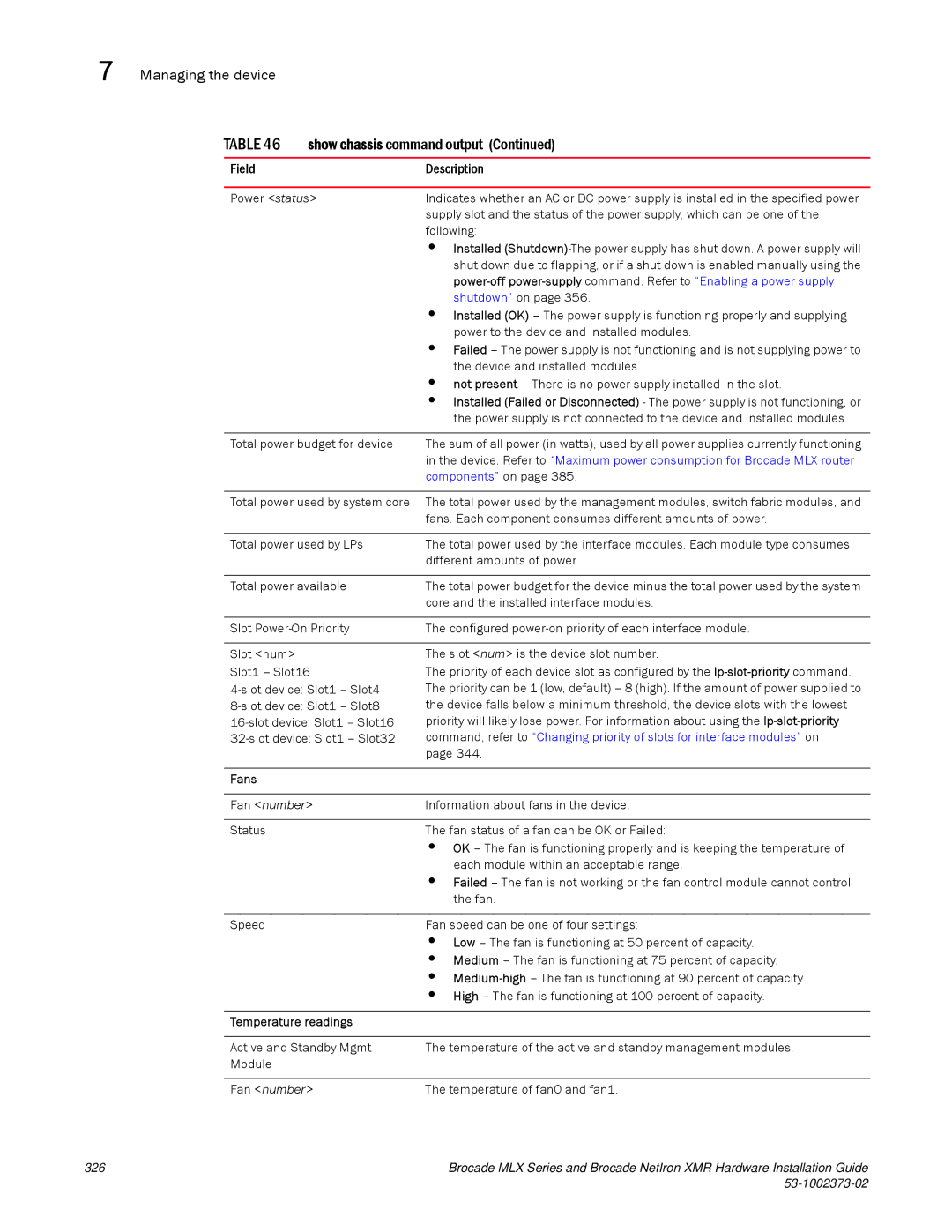
| TABLE 46 | show chassis command output (Continued) | |
|
|
|
|
|
|
| Field |
| Description |
|
|
|
| |
|
| Power <status> | Indicates whether an AC or DC power supply is installed in the specified power | |
|
|
|
| supply slot and the status of the power supply, which can be one of the |
|
|
|
| following: |
|
|
|
| • Installed |
|
|
|
| shut down due to flapping, or if a shut down is enabled manually using the |
|
|
|
| |
|
|
|
| shutdown” on page 356. |
|
|
|
| • Installed (OK) – The power supply is functioning properly and supplying |
|
|
|
| power to the device and installed modules. |
|
|
|
| • Failed – The power supply is not functioning and is not supplying power to |
|
|
|
| the device and installed modules. |
|
|
|
| • not present – There is no power supply installed in the slot. |
|
|
|
| • Installed (Failed or Disconnected) - The power supply is not functioning, or |
|
|
|
| the power supply is not connected to the device and installed modules. |
|
|
|
| |
|
| Total power budget for device | The sum of all power (in watts), used by all power supplies currently functioning | |
|
|
|
| in the device. Refer to “Maximum power consumption for Brocade MLX router |
|
|
|
| components” on page 385. |
|
|
|
| |
|
| Total power used by system core | The total power used by the management modules, switch fabric modules, and | |
|
|
|
| fans. Each component consumes different amounts of power. |
|
|
|
| |
|
| Total power used by LPs | The total power used by the interface modules. Each module type consumes | |
|
|
|
| different amounts of power. |
|
|
|
| |
|
| Total power available | The total power budget for the device minus the total power used by the system | |
|
|
|
| core and the installed interface modules. |
|
|
|
| |
|
| Slot | The configured | |
|
|
|
|
|
|
| Slot <num> |
| The slot <num> is the device slot number. |
|
| Slot1 – Slot16 | The priority of each device slot as configured by the | |
|
| The priority can be 1 (low, default) – 8 (high). If the amount of power supplied to | ||
|
| the device falls below a minimum threshold, the device slots with the lowest | ||
|
| priority will likely lose power. For information about using the | ||
|
| command, refer to “Changing priority of slots for interface modules” on | ||
|
|
|
| page 344. |
|
|
|
|
|
|
| Fans |
|
|
|
|
|
| |
|
| Fan <number> | Information about fans in the device. | |
|
|
|
|
|
|
| Status |
| The fan status of a fan can be OK or Failed: |
|
|
|
| • OK – The fan is functioning properly and is keeping the temperature of |
|
|
|
| each module within an acceptable range. |
|
|
|
| • Failed – The fan is not working or the fan control module cannot control |
|
|
|
| the fan. |
|
|
|
|
|
|
| Speed |
| Fan speed can be one of four settings: |
|
|
|
| • Low – The fan is functioning at 50 percent of capacity. |
|
|
|
| • Medium – The fan is functioning at 75 percent of capacity. |
|
|
|
| • |
|
|
|
| • High – The fan is functioning at 100 percent of capacity. |
|
|
|
| |
|
| Temperature readings |
| |
|
|
|
| |
|
| Active and Standby Mgmt | The temperature of the active and standby management modules. | |
|
| Module |
|
|
|
|
|
| |
|
| Fan <number> | The temperature of fan0 and fan1. | |
326 | Brocade MLX Series and Brocade NetIron XMR Hardware Installation Guide |
|
|