2 Installing a Brocade
10.Visually inspect the alignment of the router. If the router is installed properly in the rack, the mounting screws on one side of the rack should align with the mounting screws on the opposite side and the router should be level. Add all remaining screws.
NOTE
For better grounding of the router to the rack, attach the router using star washers. You should also use star washers with any
Installing your
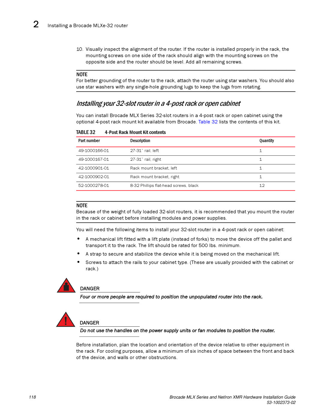
You can install Brocade MLX Series
TABLE 32 |
| ||
|
|
|
|
Part number |
| Description | Quantity |
|
|
| |
1 | |||
|
|
| |
1 | |||
|
|
| |
Rack mount bracket, left | 1 | ||
|
|
| |
Rack mount bracket, right | 1 | ||
|
|
| |
12 | |||
|
|
|
|
NOTE
Because of the weight of fully loaded
You will need the following items to install your
•A mechanical lift fitted with a lift plate (instead of forks) to move the device off the pallet and transport it to the rack. The lift should be rated for 500 lbs. minimum.
•A strap to secure and stabilize the device while it is being moved on the mechanical lift.
•Screws to attach the rails to your cabinet type. (These are usually provided with the cabinet or rack.)
DANGER
Four or more people are required to position the unpopulated router into the rack.
DANGER
Do not use the handles on the power supply units or fan modules to position the router.
Before installation, plan the location and orientation of the device relative to other equipment in the rack. For cooling purposes, allow a minimum of six inches of space between the front and back of the device, and walls or other obstructions.
118 | Brocade MLX Series and NetIron XMR Hardware Installation Guide |
|
|
