Brocade Communications Systems 53-1002373-02 manual Led

Models: 53-1002373-02

1 452
Download 452 pages 21.42 Kb
Page 75
Image 75

Router modules

1

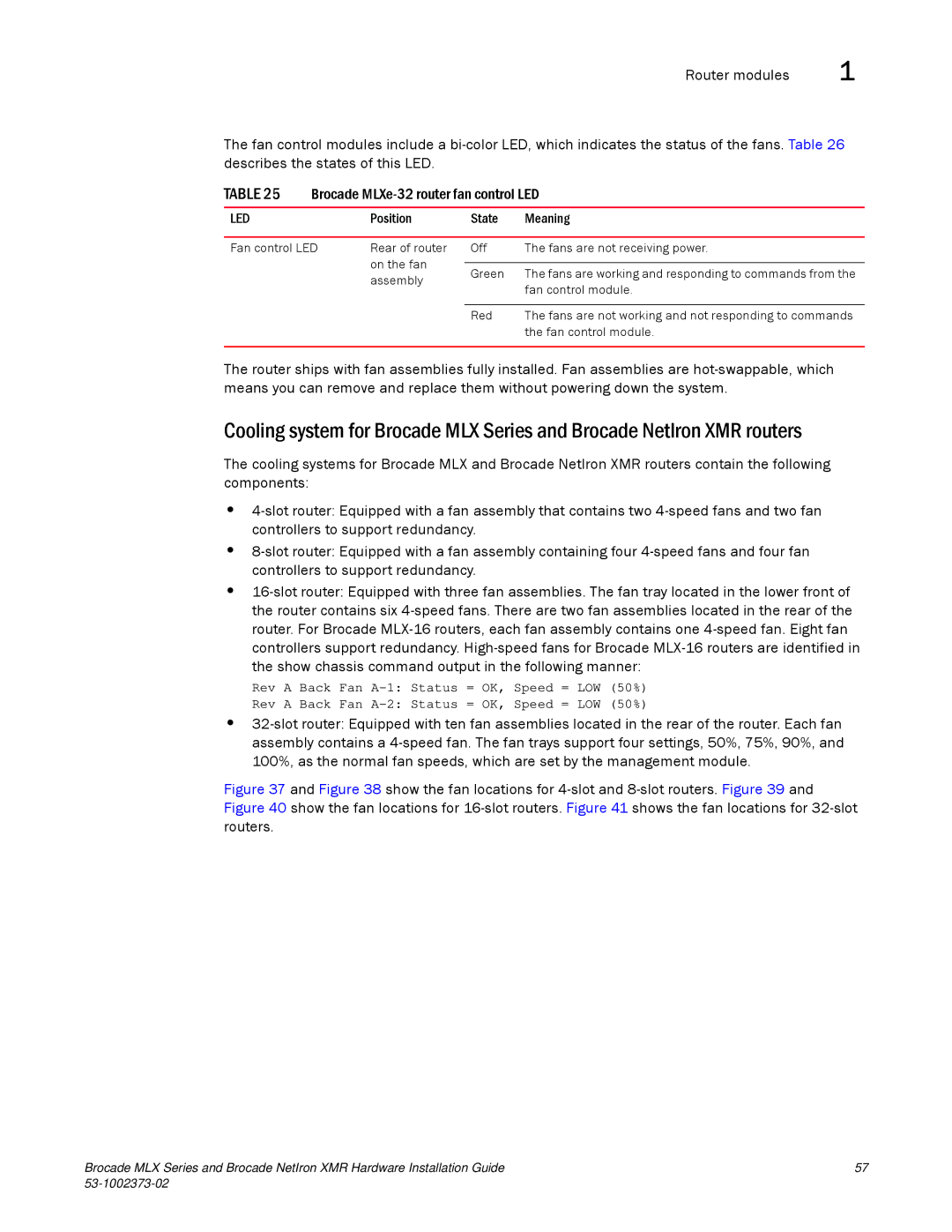
The fan control modules include a bi-color LED, which indicates the status of the fans. Table 26 describes the states of this LED.

TABLE 25

Brocade MLXe-32 router fan control LED


LED


Position

State

Meaning


Fan control LED

Rear of router

Off

The fans are not receiving power.


on the fan


Green

The fans are working and responding to commands from the


assembly


fan control module.


Red

The fans are not working and not responding to commands


the fan control module.


The router ships with fan assemblies fully installed. Fan assemblies are hot-swappable, which means you can remove and replace them without powering down the system.

Cooling system for Brocade MLX Series and Brocade NetIron XMR routers

The cooling systems for Brocade MLX and Brocade NetIron XMR routers contain the following components:

4-slot router: Equipped with a fan assembly that contains two 4-speed fans and two fan controllers to support redundancy.

8-slot router: Equipped with a fan assembly containing four 4-speed fans and four fan controllers to support redundancy.

16-slot router: Equipped with three fan assemblies. The fan tray located in the lower front of the router contains six 4-speed fans. There are two fan assemblies located in the rear of the router. For Brocade MLX-16 routers, each fan assembly contains one 4-speed fan. Eight fan controllers support redundancy. High-speed fans for Brocade MLX-16 routers are identified in the show chassis command output in the following manner:

Rev A Back Fan A-1: Status = OK, Speed = LOW (50%)

Rev A Back Fan A-2: Status = OK, Speed = LOW (50%)

32-slot router: Equipped with ten fan assemblies located in the rear of the router. Each fan assembly contains a 4-speed fan. The fan trays support four settings, 50%, 75%, 90%, and 100%, as the normal fan speeds, which are set by the management module.

Figure 37 and Figure 38 show the fan locations for 4-slot and 8-slot routers. Figure 39 and Figure 40 show the fan locations for 16-slot routers. Figure 41 shows the fan locations for 32-slot routers.

Brocade MLX Series and Brocade NetIron XMR Hardware Installation Guide

57

53-1002373-02


Page 75
Image 75
Brocade Communications Systems 53-1002373-02 manual Led