3 Installing a Brocade
•A power drill with the following attachments:
-Large #2 Phillips screwdriver attachment
-A 7/16 inch socket wrench attachment
-Large 3/8 inch flat blade screwdriver attachment
Preparing the installation site
Before installation, plan the location and orientation of the device relative to other equipment in the rack. For cooling purposes, allow a minimum of six inches of space between the front and back of the device, and walls or other obstructions.
Because you will need to use a mechanical lift to move and install the device, make sure you allow enough space to operate the lift. You will also need at least two people to slide the router off the lift and into the rack.
You can install your
Follow these initial steps to mount a
1.Ensure the rack is in a permanent location and is secured to the building. Ensure that the installation site allows adequate clearance for airflow, installation, and maintenance.
2.Move the pallet and router as close to the installation site as possible.
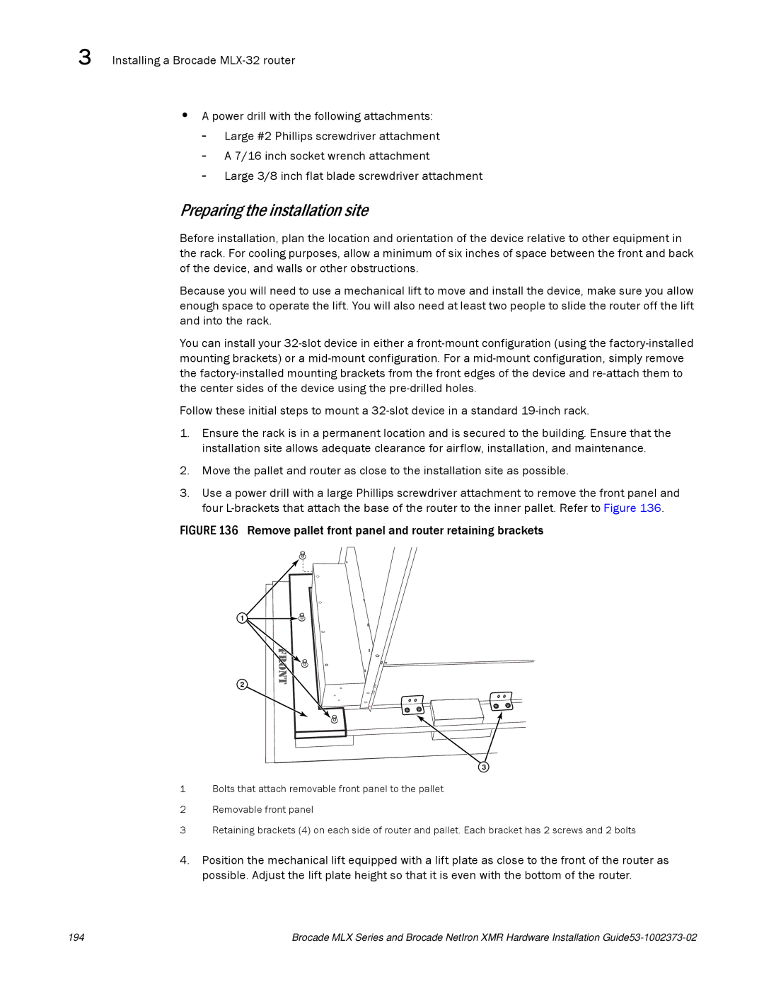
3.Use a power drill with a large Phillips screwdriver attachment to remove the front panel and four
FIGURE 136 Remove pallet front panel and router retaining brackets
1
2
3
1Bolts that attach removable front panel to the pallet
2Removable front panel
3Retaining brackets (4) on each side of router and pallet. Each bracket has 2 screws and 2 bolts
4.Position the mechanical lift equipped with a lift plate as close to the front of the router as possible. Adjust the lift plate height so that it is even with the bottom of the router.
194 | Brocade MLX Series and Brocade NetIron XMR Hardware Installation |