D. How to Use the Vent Graph

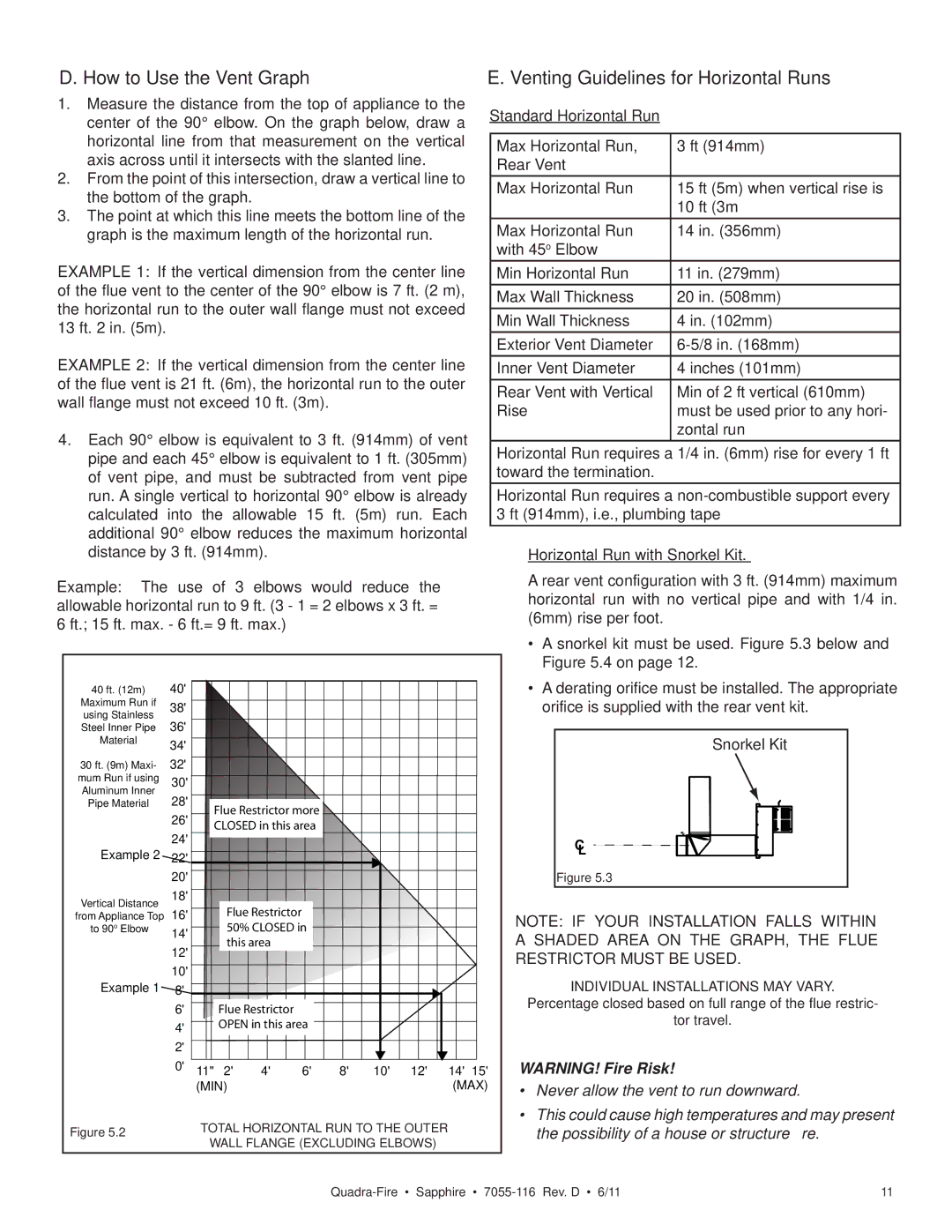
1.Measure the distance from the top of appliance to the center of the 90° elbow. On the graph below, draw a horizontal line from that measurement on the vertical axis across until it intersects with the slanted line.

2.From the point of this intersection, draw a vertical line to the bottom of the graph.

3.The point at which this line meets the bottom line of the graph is the maximum length of the horizontal run.

EXAMPLE 1: If the vertical dimension from the center line of the flue vent to the center of the 90° elbow is 7 ft. (2 m), the horizontal run to the outer wall flange must not exceed 13 ft. 2 in. (5m).

EXAMPLE 2: If the vertical dimension from the center line of the flue vent is 21 ft. (6m), the horizontal run to the outer wall flange must not exceed 10 ft. (3m).

4.Each 90° elbow is equivalent to 3 ft. (914mm) of vent pipe and each 45° elbow is equivalent to 1 ft. (305mm) of vent pipe, and must be subtracted from vent pipe run. A single vertical to horizontal 90° elbow is already calculated into the allowable 15 ft. (5m) run. Each additional 90° elbow reduces the maximum horizontal distance by 3 ft. (914mm).

Example: The use of 3 elbows would reduce the allowable horizontal run to 9 ft. (3 - 1 = 2 elbows x 3 ft. = 6 ft.; 15 ft. max. - 6 ft.= 9 ft. max.)

E. Venting Guidelines for Horizontal Runs

Standard Horizontal Run

Max Horizontal Run,

3 ft (914mm)

Rear Vent


Max Horizontal Run

15 ft (5m) when vertical rise is


10 ft (3m

Max Horizontal Run

14 in. (356mm)

with 45o Elbow


Min Horizontal Run

11 in. (279mm)

Max Wall Thickness

20 in. (508mm)

Min Wall Thickness

4 in. (102mm)

Exterior Vent Diameter

6-5/8 in. (168mm)

Inner Vent Diameter

4 inches (101mm)

Rear Vent with Vertical

Min of 2 ft vertical (610mm)

Rise

must be used prior to any hori-


zontal run

Horizontal Run requires a 1/4 in. (6mm) rise for every 1 ft toward the termination.

Horizontal Run requires a non-combustible support every 3 ft (914mm), i.e., plumbing tape

Horizontal Run with Snorkel Kit.

A rear vent configuration with 3 ft. (914mm) maximum horizontal run with no vertical pipe and with 1/4 in. (6mm) rise per foot.

40 ft. (12m)

40'


Maximum Run if

38'


using Stainless


36'


Steel Inner Pipe


Material

34'


30 ft. (9m) Maxi-

32'


mum Run if using

30'


Aluminum Inner

28'


Pipe Material


Flue Restrictor more


26'


CLOSED in this area


24'


Example 2


22'


20'


Vertical Distance

18'


Flue Restrictor


from Appliance Top

16'


to 90o Elbow

14'


50% CLOSED in


this area


12'


Example 1

10'


8'


6'


Flue Restrictor


4'


OPEN in this area


2'


0'

11"

2'

4'

6'

8'

10'

12'

14'

15'


(MIN)


(MAX)

Figure 5.2

TOTAL HORIZONTAL RUN TO THE OUTER


WALL FLANGE (EXCLUDING ELBOWS)

A snorkel kit must be used. Figure 5.3 below and

Figure 5.4 on page 12.

A derating orifice must be installed. The appropriate orifice is supplied with the rear vent kit.

Snorkel Kit

C

L

Figure 5.3

NOTE: IF YOUR INSTALLATION FALLS WITHIN A SHADED AREA ON THE GRAPH, THE FLUE RESTRICTOR MUST BE USED.

INDIVIDUAL INSTALLATIONS MAY VARY.

Percentage closed based on full range of the flue restric-

tor travel.

WARNING! Fire Risk!

Never allow the vent to run downward.

This could cause high temperatures and may present the possibility of a house or structure fire.

Quadra-Fire • Sapphire • 7055-116 Rev. D • 6/11

11

Page 11
Image 11
Quadra-Fire SAPPHIRE-D-CSB, SAPPHIRE-MBK, SAPPHIRE-D-MBK How to Use the Vent Graph, Venting Guidelines for Horizontal Runs

SAPPHIRE-D-CSB, SAPPHIRE-D-PMH, SAPPHIRE-MBK, SAPPHIRE-D-MBK specifications

The Quadra-Fire Sapphire series of fireplaces, which includes the Sapphire-D-PMH, Sapphire-D-CSB, Sapphire-D-MBK, and Sapphire-MBK models, epitomizes modern heating technology combined with elegant design. These units are meticulously engineered to enhance both efficiency and aesthetics, making them perfect additions to contemporary living spaces.

One of the standout features of the Sapphire series is its advanced combustion technology. The fireplaces utilize a patented Clean Burn technology. This innovation ensures that the combustion process is as efficient as possible, resulting in reduced emissions and maximizing heat output. With lower particulate emissions, these models not only provide warmth but do so in an environmentally conscious manner.

In terms of performance, the Sapphire fireplaces are designed to deliver consistent and radiant heat. With their powerful heating capabilities, they can warm up large areas, making them suitable for homes of various sizes. The efficient design helps to distribute heat evenly throughout a room, eliminating cold spots and ensuring comfort in all corners of your living space.

The design aesthetics of the Sapphire series is equally impressive. The models feature a sleek, modern design complemented by a large viewing area, allowing for an unobstructed view of the mesmerizing flames. The glass is designed to remain clean for longer periods, thanks to the sophisticated airflow management system that directs air over the glass surfaces, reducing soot buildup.

Customization options are another notable characteristic of the Sapphire series. Homeowners can choose from various finishes and styles to match their home’s decor. The units are available in both traditional and contemporary designs, allowing for versatility in different architectural settings.

The Sapphire-D-PMH model is equipped with a programmable thermostat for added convenience and efficiency. This technology allows users to set the desired temperature, ensuring that their space remains comfortable without unnecessary manual adjustments.

On the other hand, the Sapphire-D-CSB model features an innovative fuel management system that optimally uses wood fuel for extended burn times. This means less frequent refueling and more time spent enjoying the warmth and ambiance the fireplace provides.

The Sapphire-D-MBK and Sapphire-MBK models are designed with durability and longevity in mind. Each unit is constructed from high-quality materials that are built to withstand extreme temperatures while maintaining structural integrity over time.

In summary, the Quadra-Fire Sapphire series combines advanced technology, unique design, and high efficiency. With features like Clean Burn technology, customizable options, and smart fuel management systems, the Sapphire fireplaces offer not just heat, but a stylish centerpiece for modern homes.