G


R


v


D


A

H


v

E


L

B


U.S.


v


B


v

B

(3 FT)


v


F

v


v

I

M

v


X


A


J or K

M

N

P

Q

(See Note 2)

V

T

VS Electrical Service

D*

V

S V

V

= VENT TERMINAL

X = AIR SUPPLY INLET

= AREA WHERE TERMINAL IS NOT PERMITTED

A

=

12 inches

clearances above grade, veran-

K


=

3 ft. (U.S.A.)


(See Note 1)

da, porch, deck or balcony


6 ft. (Canada)

clearance to a mechanical


B

=

12 inches

clearances to window or door


(powered) air supply inlet


L**

=

7 ft

clearance

above paved


that may be opened, or to per-


(See Note 1)

sidewalk or a paved driveway


manently closed window. (Glass)


located on public property


D*

=

18 inches

vertical clearance to unventilat-

M*** =

18 inches

clearance

under veranda ,


ed soffit or to ventilated soffit lo-


porch, deck, balcony or over-


cated above the terminal


hang


*30 inches

for vinyl clad soffits and below


42 inches

vinyl


electrical service

S

=


6 inches

clearance from sides of


F

=

9 inches

clearance to outside corner


(See Note 3)

electrical service


G

=

6 inches

clearance to inside corner

T

=


12 inches

clearance above electrical


H

=

3 ft. (Canada)

not to be installed above a gas


(See Note 3)

service


meter/regulatorassembly within 3


Alcove Applications


feet (90cm) horizontally from the


N


=

6 inches

non-vinyl sidewalls


center-line of the regulator


12 inches

vinyl sidewalls


I

=

3 ft

clearance to gas service regula-


P


=

8 ft.


QMIN


RMAX


tor vent outlet


J

=

9 inches (U.S.A.)


1 cap


3 feet


2 x Q ACTUA L


12 inches (Canada)clearance to non-mechanical air


2 caps


6 feet


1 x Q ACTUA L


supply inlet to building or the


3 caps


9 feet


2/3 x Q ACTUA L


combustion air inlet to any other


4 caps


12 feet


1/2 x Q ACTUA L


appliance


QMIN = # termination caps X 3 RMAX = (2 / # termination caps) x QACTUAL


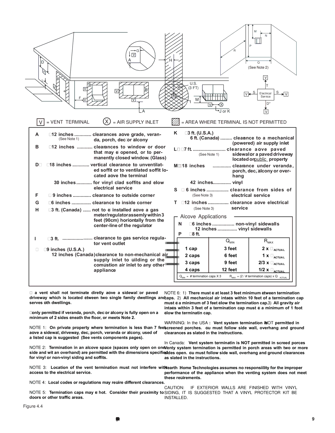
**a vent shall not terminate diretly above a sidewalk or paved driveway which is located between two single family dwellings and serves both dwellings.

***only permitted if veranda, porch, deck or balcony is fully open on a minimum of 2 sides beneath the floor, or meets Note 2.

NOTE 1: On private property where termination is less than 7 feet above a sidewalk, driveway, deck, porch, veranda or balcony, used of a listed cap is suggested (See vents components pages).

NOTE 2: Termination in an alcove space (spaces only open on one side and wit an overhand) are permitted with the dimensions specified for vinyl or non-vinyl siding and soffits.

NOTE 3: Location of the vent termination must not interfere with access to the electrical service.

NOTE 4: Local codes or regulations may require different clearances.

NOTE 5: Termination caps may be hot. Consider their proximity to doors or other traffic areas.

Figure 4.4

NOTE 6: 1) There must be at least 3 feet minimum between termination caps. 2) All mechanical air intakes within 10 feet of a termination cap must be a minimum of 3 feet below the termination cap. 3) All gravity air intakes within 3 feet of a termination cap must be a minimum of 1 foot below the terminatin cap.

WARNING: In the USA: Vent system termination is NOT permitted in screened porches. You must follow side wall, overhang and ground clearances as slated in the instructions.

In Canada: Vent system terminatin is NOT permitted in screed porces Venty system termination is permitted in porch areas with two or more sides open. You must follow side wall, overhang and ground clearances as slated in the instructions.

Hearth & Home Technologies assumes no responsibility for the improper performance of the appliance when the venting system does not meet these requirements.

CAUTION: IF EXTERIOR WALLS ARE FINISHED WITH VINYL SIDING, IT IS SUGGESTED THAT A VINYL PROTECTOR KIT BE INSTALLED.

Quadra-Fire • Sapphire • 7055-116 Rev. D • 6/11

9

Page 9
Image 9
Quadra-Fire SAPPHIRE-D-MBK, SAPPHIRE-MBK, SAPPHIRE-D-PMH, SAPPHIRE-D-CSB owner manual Alcove Applications

SAPPHIRE-D-CSB, SAPPHIRE-D-PMH, SAPPHIRE-MBK, SAPPHIRE-D-MBK specifications

The Quadra-Fire Sapphire series of fireplaces, which includes the Sapphire-D-PMH, Sapphire-D-CSB, Sapphire-D-MBK, and Sapphire-MBK models, epitomizes modern heating technology combined with elegant design. These units are meticulously engineered to enhance both efficiency and aesthetics, making them perfect additions to contemporary living spaces.

One of the standout features of the Sapphire series is its advanced combustion technology. The fireplaces utilize a patented Clean Burn technology. This innovation ensures that the combustion process is as efficient as possible, resulting in reduced emissions and maximizing heat output. With lower particulate emissions, these models not only provide warmth but do so in an environmentally conscious manner.

In terms of performance, the Sapphire fireplaces are designed to deliver consistent and radiant heat. With their powerful heating capabilities, they can warm up large areas, making them suitable for homes of various sizes. The efficient design helps to distribute heat evenly throughout a room, eliminating cold spots and ensuring comfort in all corners of your living space.

The design aesthetics of the Sapphire series is equally impressive. The models feature a sleek, modern design complemented by a large viewing area, allowing for an unobstructed view of the mesmerizing flames. The glass is designed to remain clean for longer periods, thanks to the sophisticated airflow management system that directs air over the glass surfaces, reducing soot buildup.

Customization options are another notable characteristic of the Sapphire series. Homeowners can choose from various finishes and styles to match their home’s decor. The units are available in both traditional and contemporary designs, allowing for versatility in different architectural settings.

The Sapphire-D-PMH model is equipped with a programmable thermostat for added convenience and efficiency. This technology allows users to set the desired temperature, ensuring that their space remains comfortable without unnecessary manual adjustments.

On the other hand, the Sapphire-D-CSB model features an innovative fuel management system that optimally uses wood fuel for extended burn times. This means less frequent refueling and more time spent enjoying the warmth and ambiance the fireplace provides.

The Sapphire-D-MBK and Sapphire-MBK models are designed with durability and longevity in mind. Each unit is constructed from high-quality materials that are built to withstand extreme temperatures while maintaining structural integrity over time.

In summary, the Quadra-Fire Sapphire series combines advanced technology, unique design, and high efficiency. With features like Clean Burn technology, customizable options, and smart fuel management systems, the Sapphire fireplaces offer not just heat, but a stylish centerpiece for modern homes.