7.Tightening the gib screws should be done in increments, to prevent any distortion to the cutterhead or buckling of knives. While holding the gauge down on one knife, snug down the five gib screws, beginning with the center screw and working your way to the ends. Do not fully tighten yet.
8.Rotate the cutterhead to the next slot and repeat step #6, only making the knives snug. Repeat for the third knife.
9.The tightening process should continue at least two more times, each time tightening the screws more on all three knives. On the third time, they should all be firmly tightened.
![]() Before starting jointer, make sure all gib screws are firmly tightened. A loose knife thrown from the cutterhead can cause severe or fatal injury.
Before starting jointer, make sure all gib screws are firmly tightened. A loose knife thrown from the cutterhead can cause severe or fatal injury.
10.After replacing knives, the outfeed table must be checked and adjusted so that it is level with the high point of the knives. See “Setting Outfeed Table” on page 16.
Leveling Tables
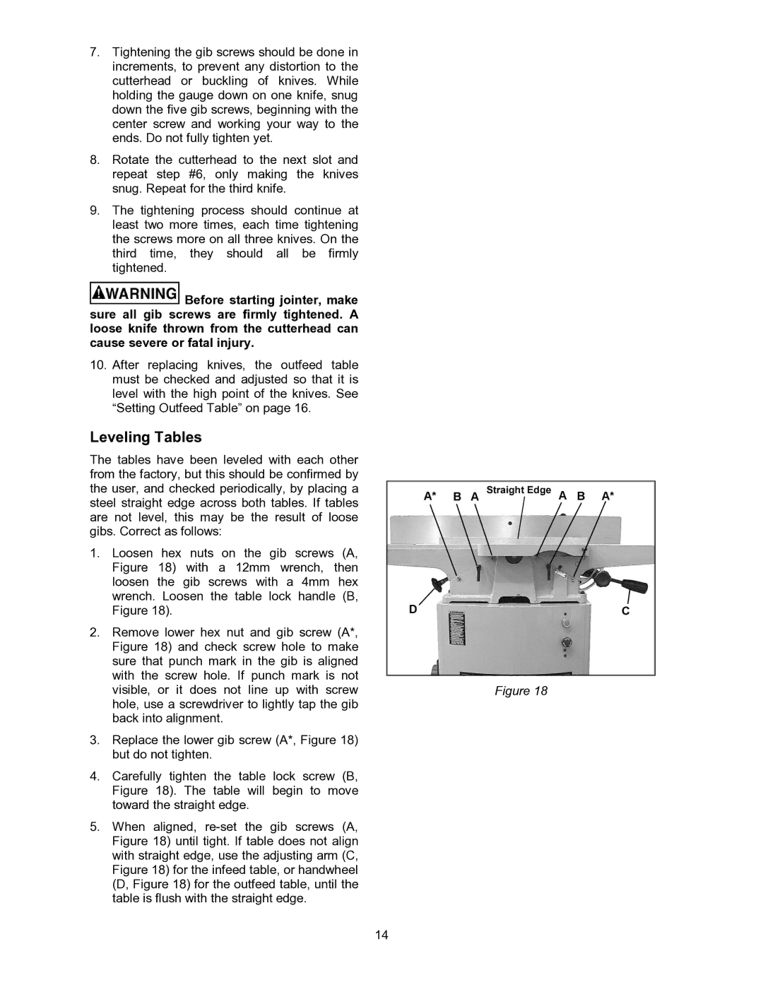
The tables have been leveled with each other from the factory, but this should be confirmed by the user, and checked periodically, by placing a steel straight edge across both tables. If tables are not level, this may be the result of loose gibs. Correct as follows:
1.Loosen hex nuts on the gib screws (A, Figure 18) with a 12mm wrench, then loosen the gib screws with a 4mm hex wrench. Loosen the table lock handle (B, Figure 18).
2.Remove lower hex nut and gib screw (A*, Figure 18) and check screw hole to make sure that punch mark in the gib is aligned with the screw hole. If punch mark is not
visible, or it does not line up with screw | Figure 18 |
hole, use a screwdriver to lightly tap the gib |
|
back into alignment. |
|
3.Replace the lower gib screw (A*, Figure 18) but do not tighten.
4.Carefully tighten the table lock screw (B, Figure 18). The table will begin to move toward the straight edge.
5.When aligned,
14