Receiving
Open shipping container and check for shipping damage. Report any damage immediately to your distributor and shipping agent. Do not discard any shipping material until the Rip Saw is installed and running properly.
Compare the contents of your container with the following parts list to make sure all parts are intact. Missing parts, if any, should be reported to your distributor. Read the instruction manual thoroughly for assembly, maintenance and safety instructions.
Contents of crate:
1Rip saw body
1Rip fence
1Blade
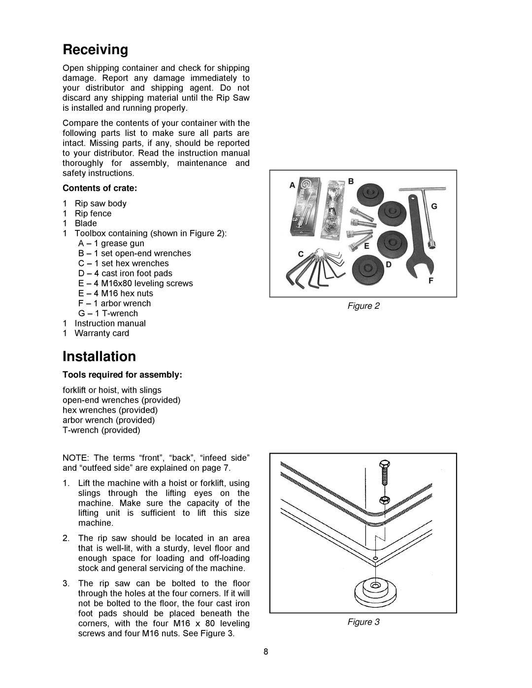
1Toolbox containing (shown in Figure 2): A – 1 grease gun
B – 1 set
D – 4 cast iron foot pads
E – 4 M16x80 leveling screws E – 4 M16 hex nuts
F – 1 arbor wrench G – 1
1Instruction manual
1Warranty card
Installation
Tools required for assembly:
forklift or hoist, with slings
NOTE: The terms “front”, “back”, “infeed side” and “outfeed side” are explained on page 7.
1.Lift the machine with a hoist or forklift, using slings through the lifting eyes on the machine. Make sure the capacity of the lifting unit is sufficient to lift this size machine.
2.The rip saw should be located in an area that is
3.The rip saw can be bolted to the floor through the holes at the four corners. If it will not be bolted to the floor, the four cast iron foot pads should be placed beneath the corners, with the four M16 x 80 leveling screws and four M16 nuts. See Figure 3.
8
Figure 2
Figure 3