SECTION 5 − INSTALLATION
5-1. Installing Nozzle, Contact Tip, And Adapter
|
|
| ! | Turn | off | welding | power |
|
|
|
| source. |
|
| |
|
|
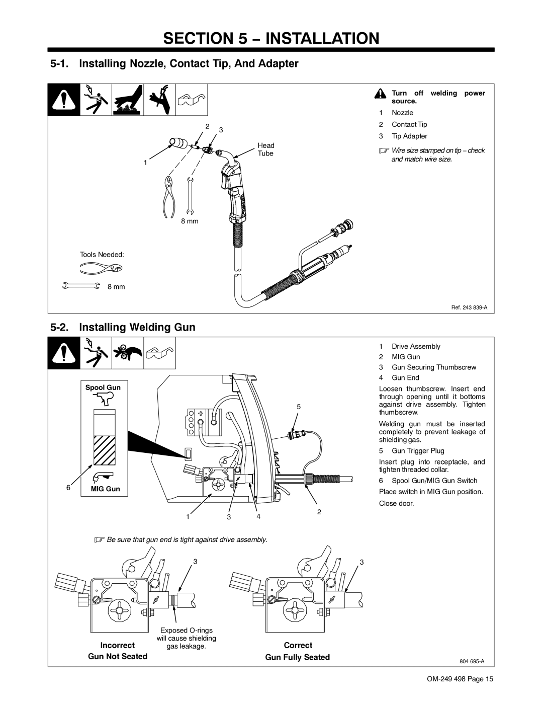
| 1 | Nozzle |
|
|
|
2 | 3 |
| 2 | Contact Tip |
|
| |
|
| 3 | Tip Adapter |
|
| ||
|
|
|
|
| |||
|
| Head | . Wire size stamped on tip − check | ||||
|
| Tube | |||||
|
|
| and match wire size. |
| |||
1 |
|
|
|
| |||
|
|
|
|
|
|
| |
8 mm |
|
|
|
|
|
|
|
Tools Needed: |
|
|
|
|
|
|
|
8 mm |
|
|
|
|
|
|
|
|
|
|
|
|
| Ref. 243 | |
|
|
|
|
|
|
|
|
Spool Gun
MIG Gun
1 | 3 | 4 |
.Be sure that gun end is tight against drive assembly.
3
5
2
3
1Drive Assembly
2MIG Gun
3Gun Securing Thumbscrew
4Gun End
Loosen thumbscrew. Insert end through opening until it bottoms against drive assembly. Tighten thumbscrew.
Welding gun must be inserted completely to prevent leakage of shielding gas.
5 Gun Trigger Plug
Insert plug into receptacle, and tighten threaded collar.
6Spool Gun/MIG Gun Switch Place switch in MIG Gun position. Close door.
| Exposed |
|
|
Incorrect | will cause shielding | Correct |
|
gas leakage. |
| ||
Gun Not Seated |
| Gun Fully Seated | 804 |
|
|
|
