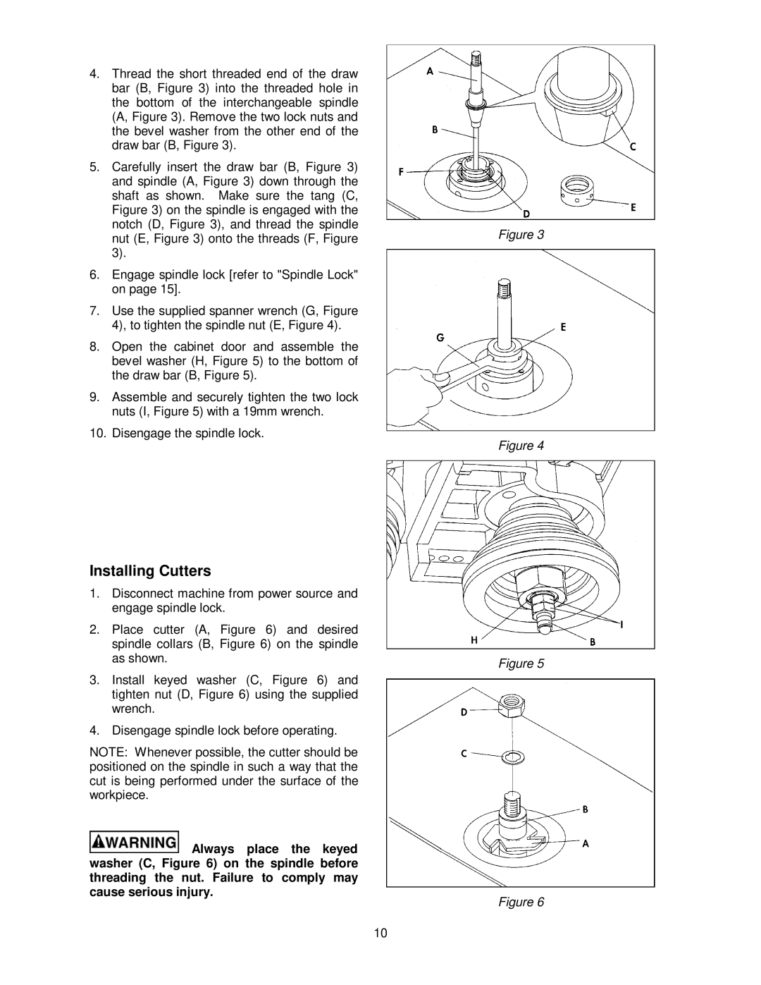
4.Thread the short threaded end of the draw bar (B, Figure 3) into the threaded hole in the bottom of the interchangeable spindle (A, Figure 3). Remove the two lock nuts and the bevel washer from the other end of the draw bar (B, Figure 3).
5.Carefully insert the draw bar (B, Figure 3) and spindle (A, Figure 3) down through the shaft as shown. Make sure the tang (C, Figure 3) on the spindle is engaged with the notch (D, Figure 3), and thread the spindle nut (E, Figure 3) onto the threads (F, Figure 3).
6.Engage spindle lock [refer to "Spindle Lock" on page 15].
7.Use the supplied spanner wrench (G, Figure 4), to tighten the spindle nut (E, Figure 4).
8.Open the cabinet door and assemble the bevel washer (H, Figure 5) to the bottom of the draw bar (B, Figure 5).
9.Assemble and securely tighten the two lock nuts (I, Figure 5) with a 19mm wrench.
10.Disengage the spindle lock.
Figure 3
Figure 4
Installing Cutters
1.Disconnect machine from power source and engage spindle lock.
2.Place cutter (A, Figure 6) and desired spindle collars (B, Figure 6) on the spindle as shown.
3.Install keyed washer (C, Figure 6) and tighten nut (D, Figure 6) using the supplied wrench.
4.Disengage spindle lock before operating.
NOTE: Whenever possible, the cutter should be positioned on the spindle in such a way that the cut is being performed under the surface of the workpiece.
![]() Always place the keyed washer (C, Figure 6) on the spindle before threading the nut. Failure to comply may cause serious injury.
Always place the keyed washer (C, Figure 6) on the spindle before threading the nut. Failure to comply may cause serious injury.
10
Figure 5
Figure 6