Operating Controls
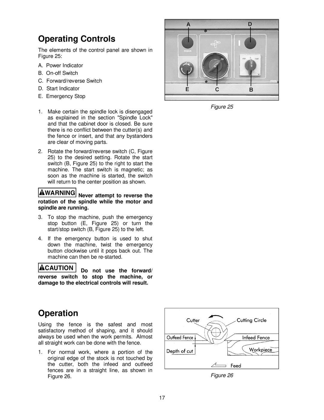
The elements of the control panel are shown in Figure 25:
A.Power Indicator
B.
C.Forward/reverse Switch
D.Start Indicator
E.Emergency Stop
1.Make certain the spindle lock is disengaged as explained in the section "Spindle Lock" and that the cabinet door is closed. Be sure there is no conflict between the cutter(s) and the fence or insert, and that any bystanders are clear of moving parts.
2.Rotate the forward/reverse switch (C, Figure
25)to the desired setting. Rotate the start switch (B, Figure 25) to the right to start the machine. The start switch is magnetic; as soon as the machine is started, the switch will return to the center position as shown.
![]() Never attempt to reverse the rotation of the spindle while the motor and spindle are running.
Never attempt to reverse the rotation of the spindle while the motor and spindle are running.
3.To stop the machine, push the emergency stop button (E, Figure 25) or turn the start/stop switch (B, Figure 25) to the left.
4.If the emergency button is used to shut down the machine, twist the emergency button clockwise until it pops back out. The machine can then be
![]() Do not use the forward/ reverse switch to stop the machine, or damage to the electrical controls will result.
Do not use the forward/ reverse switch to stop the machine, or damage to the electrical controls will result.
Operation
Using the fence is the safest and most satisfactory method of shaping, and it should always be used when the work permits. Almost all straight work can be done with the fence.
1.For normal work, where a portion of the original edge of the stock is not touched by the cutter, both the infeed and outfeed fences are in a straight line, as shown in Figure 26.
17
Figure 25
Figure 26
