To adjust the infeed roller:
1.Disconnect machine from power source.
2.Place a dial gauge (not provided) under a knife insert in the cutterhead. If a dial gauge is not available, use a finished block of wood with notches cut out for the table rollers, in conjunction with a feeler gauge. See Figure 10 for an example of a wood block you can make and use as a gauge.
3.Raise the table with the handwheel until the gauge contacts a knife insert at the apex of its curve. Zero the gauge at that position.
4.Move the gauge to the extreme left side of the infeed roller and check the measurement. It should be 1/16” below the knife measurement.
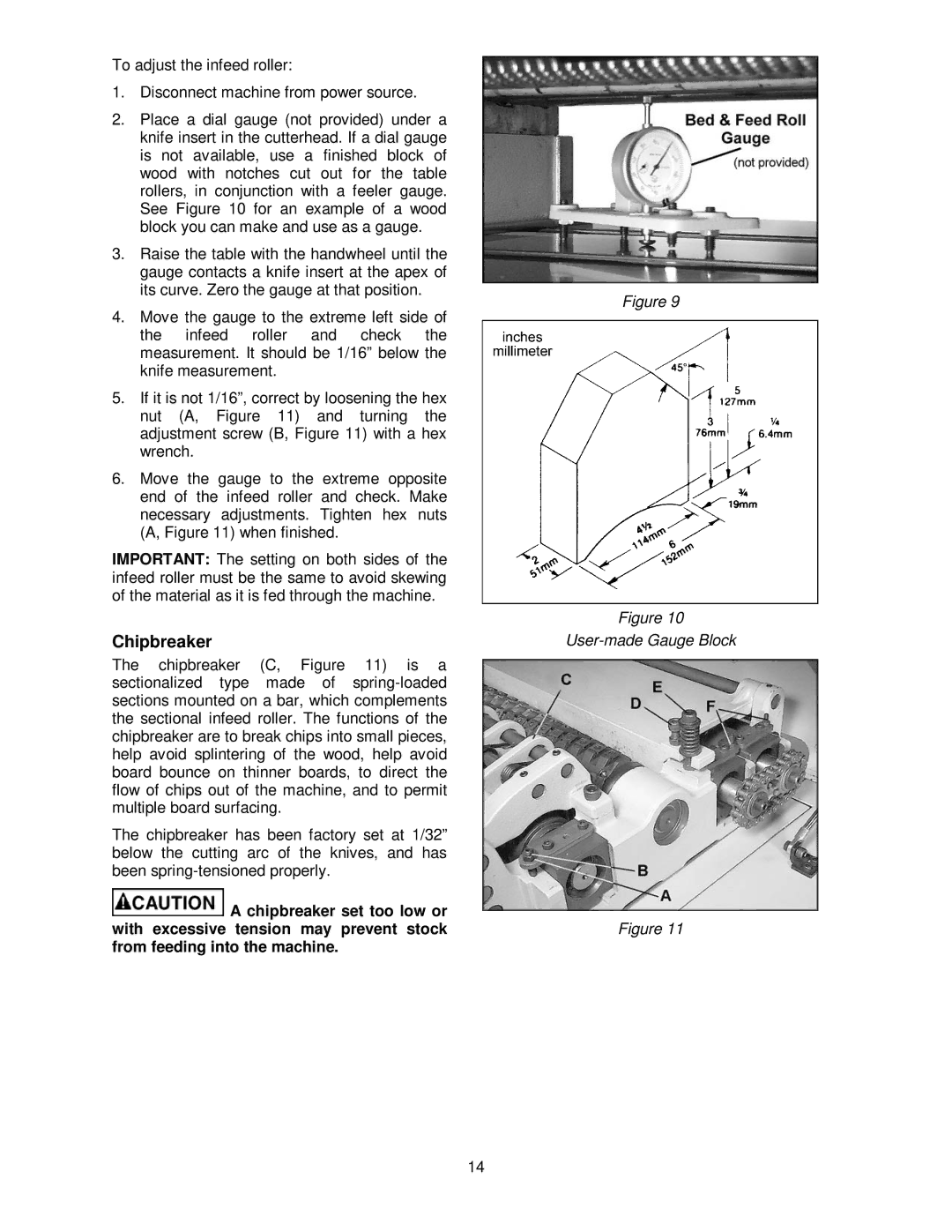
5.If it is not 1/16”, correct by loosening the hex nut (A, Figure 11) and turning the adjustment screw (B, Figure 11) with a hex wrench.
6.Move the gauge to the extreme opposite end of the infeed roller and check. Make necessary adjustments. Tighten hex nuts (A, Figure 11) when finished.
IMPORTANT: The setting on both sides of the infeed roller must be the same to avoid skewing of the material as it is fed through the machine.
Chipbreaker
The chipbreaker (C, Figure 11) is a sectionalized type made of
The chipbreaker has been factory set at 1/32” below the cutting arc of the knives, and has been
![]() A chipbreaker set too low or with excessive tension may prevent stock from feeding into the machine.
A chipbreaker set too low or with excessive tension may prevent stock from feeding into the machine.
Figure 9
Figure 10
Figure 11
14