Pressure Bar |
| |
Most planing problems can be traced to |
| |
improper setting of the pressure bar. Its function |
| |
is to hold down the material after it passes under |
| |
the cutterhead and throughout the remainder of |
| |
the cut. Its basic setting is to be in line with the |
| |
arc of the cutterhead knives. |
| |
If it is too high, a shallow “clip” will occur at each |
| |
end of the board. If it is too low, stock will not |
| |
feed through. |
| |
Use a gauge to set the full length of the |
| |
pressure bar to |
| |
arc of the cutterhead. Figure 11 shows the |
| |
height adjustment screw (D) and the spring |
| |
tension adjustment screw (E) for the pressure |
| |
bar. This initial setup is a starting point and final |
| |
adjustment may have to be made during a test |
| |
cut. |
| |
Outfeed Rollers |
| |
The two outfeed rollers are of smooth, |
| |
construction to help avoid marring the finished |
| |
surface of the material being cut. Their function |
| |
is to continue to feed the material through the |
| |
machine after it leaves the infeed roller. The |
| |
correct free position setting is 1/32” (.8mm) |
| |
below the arc of the cutterhead knives. |
| |
Use a gauge, such as a bed and feed roll gauge |
| |
or wood gauge block, to check the outfeed |
| |
rollers in the same manner as the infeed roller. |
| |
Adjust as necessary using the screws (F, Figure |
| |
11). When finished adjusting, tighten the hex |
| |
nuts on the screws (F, Figure 11). |
| |
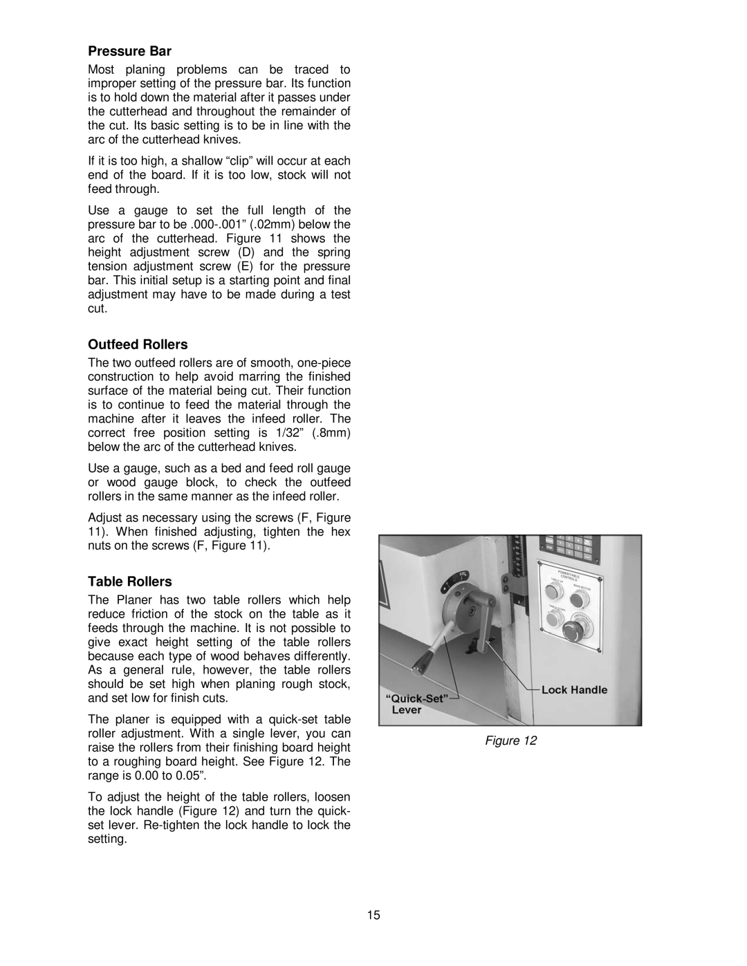
Table Rollers |
| |
The Planer has two table rollers which help |
| |
reduce friction of the stock on the table as it |
| |
feeds through the machine. It is not possible to |
| |
give exact height setting of the table rollers |
| |
because each type of wood behaves differently. |
| |
As a general rule, however, the table rollers |
| |
should be set high when planing rough stock, |
| |
and set low for finish cuts. |
| |
The planer is equipped with a |
| |
roller adjustment. With a single lever, you can | Figure 12 | |
raise the rollers from their finishing board height | ||
| ||
to a roughing board height. See Figure 12. The |
| |
range is 0.00 to 0.05”. |
| |
To adjust the height of the table rollers, loosen |
| |
the lock handle (Figure 12) and turn the quick- |
| |
set lever. |
| |
setting. |
|
15