C O M M E R C I A L | P R O D U C T S | D I V I S I O N |
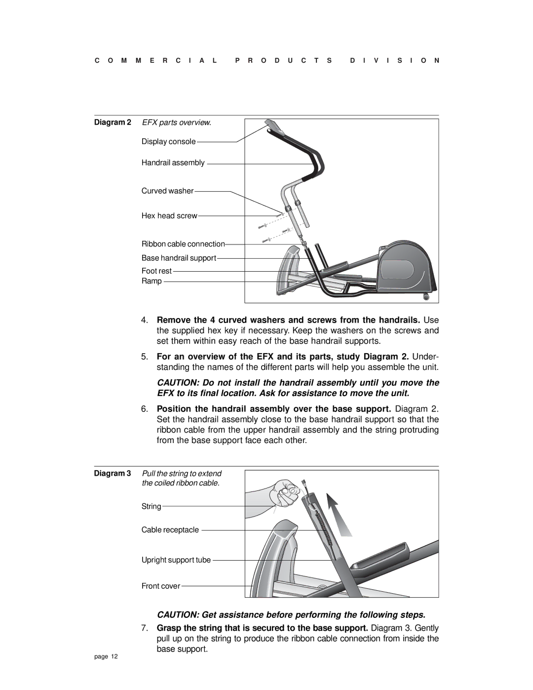
Diagram 2 EFX parts overview. |
|
|
Display console |
|
|
Handrail assembly |
|
|
Curved washer |
|
|
Hex head screw |
|
|
Ribbon cable connection |
|
|
Base handrail support |
|
|
Foot rest |
|
|
Ramp |
|
|
4.Remove the 4 curved washers and screws from the handrails. Use the supplied hex key if necessary. Keep the washers on the screws and set them within easy reach of the base handrail supports.
5.For an overview of the EFX and its parts, study Diagram 2. Under- standing the names of the different parts will help you assemble the unit.
CAUTION: Do not install the handrail assembly until you move the EFX to its final location. Ask for assistance to move the unit.
6.Position the handrail assembly over the base support. Diagram 2. Set the handrail assembly close to the base handrail support so that the ribbon cable from the upper handrail assembly and the string protruding from the base support face each other.
Diagram 3 Pull the string to extend the coiled ribbon cable.
String
Cable receptacle
Upright support tube
Front cover
CAUTION: Get assistance before performing the following steps.
7.Grasp the string that is secured to the base support. Diagram 3. Gently pull up on the string to produce the ribbon cable connection from inside the base support.
page 12
