I V . A S S E M B L Y / D I S A S S E M B L Y |
TOGGLE LATCH |
RELEASE BUTTON |
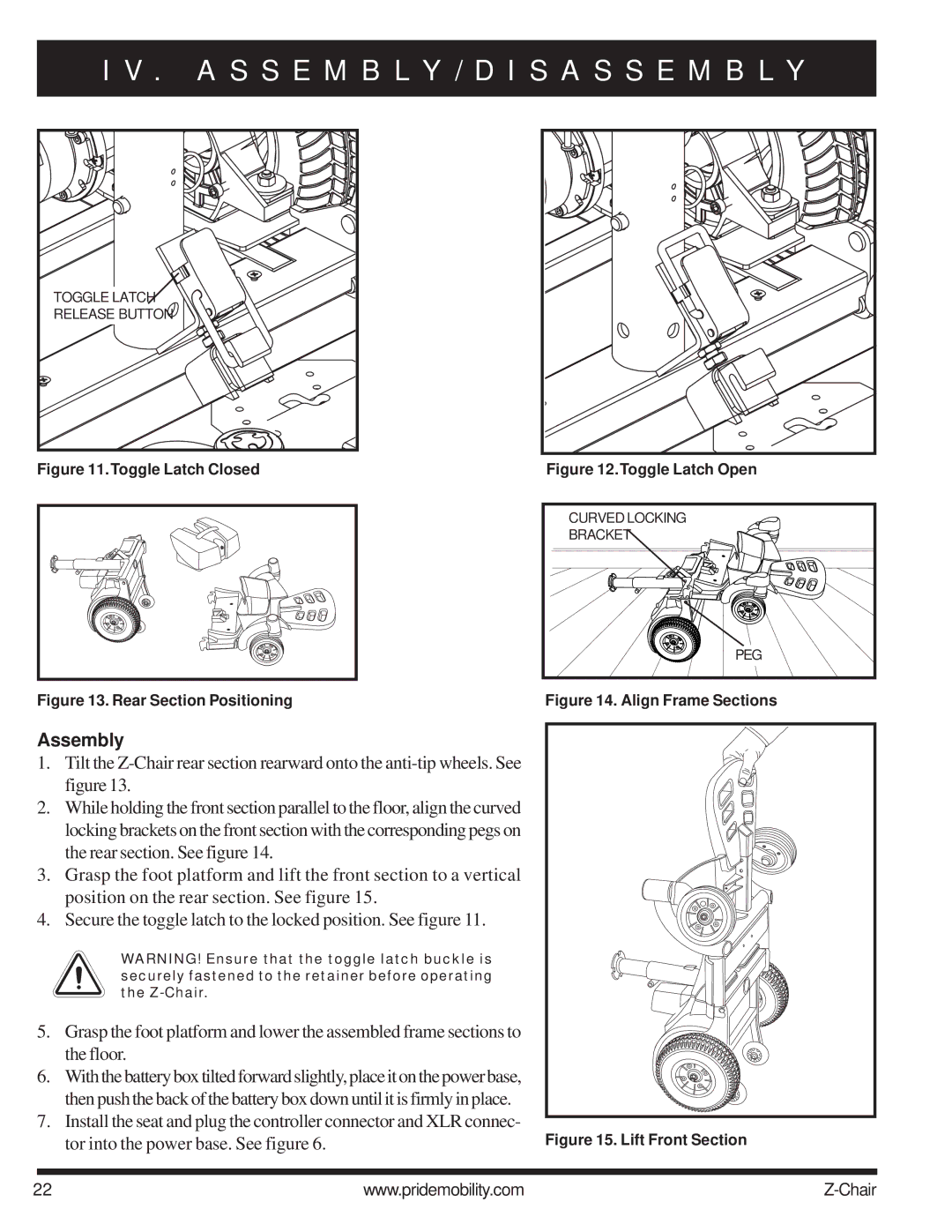
Figure 11.Toggle Latch Closed | Figure 12.Toggle Latch Open |
CURVEDLOCKING |
BRACKET |
PEG |
Figure 13. Rear Section Positioning | Figure 14. Align Frame Sections |
Assembly
1.Tilt the
2.While holding the front section parallel to the floor, align the curved
locking brackets on the front section with the corresponding pegs on the rear section. See figure 14.
3. Grasp the foot platform and lift the front section to a vertical position on the rear section. See figure 15.
4. Secure the toggle latch to the locked position. See figure 11.
WARNING! Ensure that the toggle latch buckle is securely fastened to the retainer before operating the
5. | Grasp the foot platform and lower the assembled frame sections to |
|
| the floor. |
|
6. | Withthebatteryboxtiltedforwardslightly,placeitonthepowerbase, |
|
| then push the back of the battery box down until it is firmly in place. |
|
7. | Install the seat and plug the controller connector and XLR connec- | Figure 15. Lift Front Section |
| tor into the power base. See figure 6. |
22 | www.pridemobility.com |
