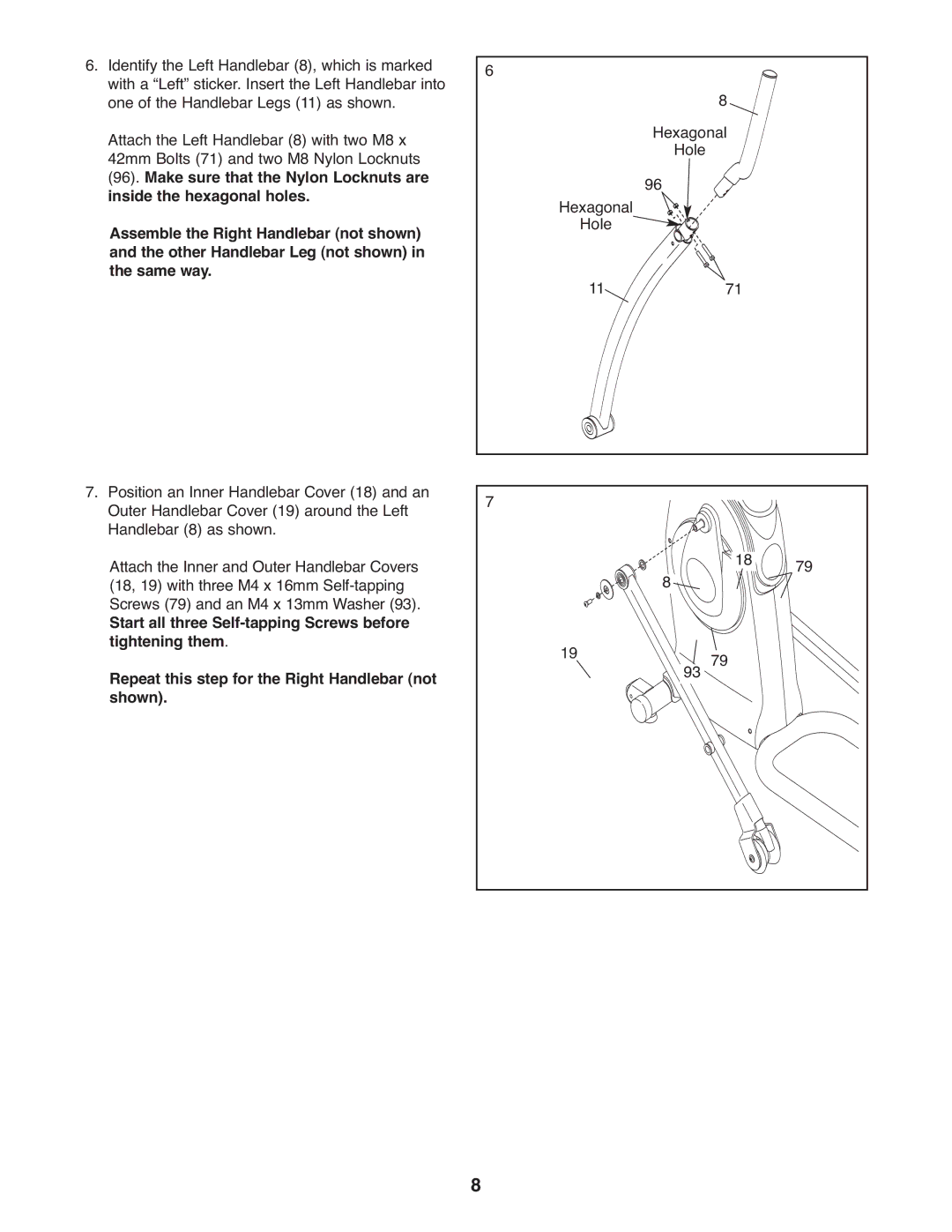
6.Identify the Left Handlebar (8), which is marked with a “Left” sticker. Insert the Left Handlebar into one of the Handlebar Legs (11) as shown. Attach the Left Handlebar (8) with two M8 x 42mm Bolts (71) and two M8 Nylon Locknuts (96). Make sure that the Nylon Locknuts are inside the hexagonal holes.
Assemble the Right Handlebar (not shown) and the other Handlebar Leg (not shown) in the same way.
6
8
Hexagonal ![]() Hole
Hole
Hexagonal 96 Hole ![]()
![]()
![]()
![]()
11![]()
![]() 71
71
7.Position an Inner Handlebar Cover (18) and an Outer Handlebar Cover (19) around the Left Handlebar (8) as shown.
Attach the Inner and Outer Handlebar Covers (18, 19) with three M4 x 16mm
Start all three
Repeat this step for the Right Handlebar (not shown).
7
8 | 18 | 79 |
|
|
19![]()
![]()
![]()
![]()
![]()
![]()
![]()
![]() 93 79
93 79
8