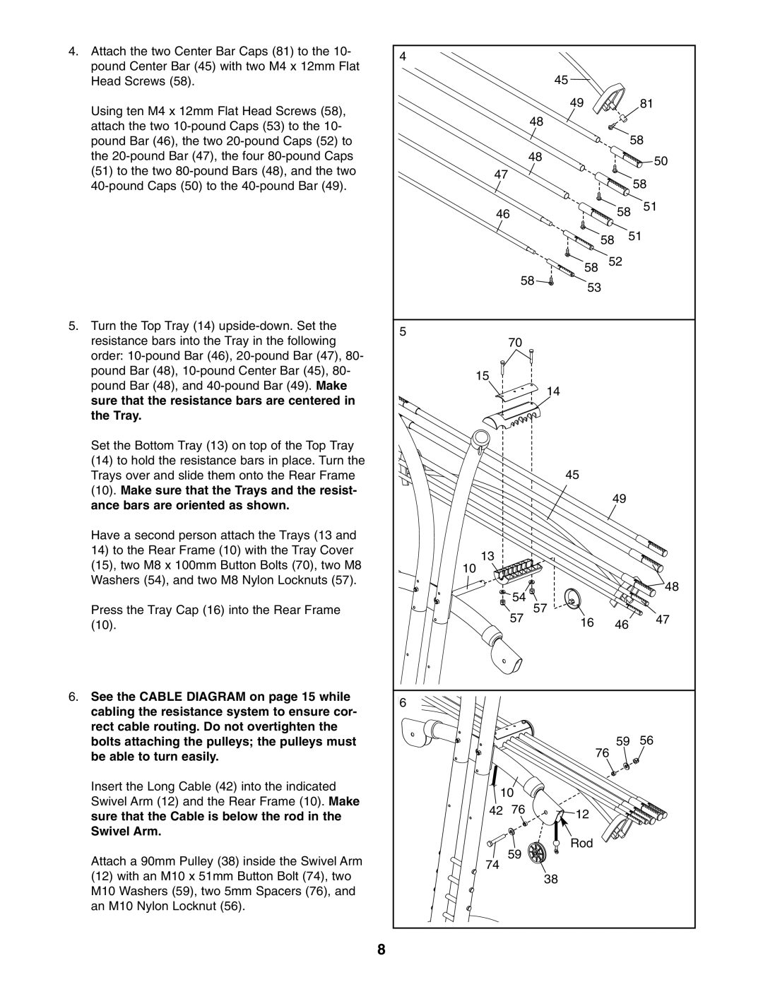
4.Attach the two Center Bar Caps (81) to the 10- pound Center Bar (45) with two M4 x 12mm Flat Head Screws (58).
Using ten M4 x 12mm Flat Head Screws (58), attach the two
5.Turn the Top Tray (14)
Set the Bottom Tray (13) on top of the Top Tray
(14)to hold the resistance bars in place. Turn the Trays over and slide them onto the Rear Frame
(10).Make sure that the Trays and the resist- ance bars are oriented as shown.
Have a second person attach the Trays (13 and
14)to the Rear Frame (10) with the Tray Cover (15), two M8 x 100mm Button Bolts (70), two M8 Washers (54), and two M8 Nylon Locknuts (57).
Press the Tray Cap (16) into the Rear Frame (10).
6.See the CABLE DIAGRAM on page 15 while cabling the resistance system to ensure cor- rect cable routing. Do not overtighten the bolts attaching the pulleys; the pulleys must be able to turn easily.
Insert the Long Cable (42) into the indicated Swivel Arm (12) and the Rear Frame (10). Make sure that the Cable is below the rod in the Swivel Arm.
Attach a 90mm Pulley (38) inside the Swivel Arm (12) with an M10 x 51mm Button Bolt (74), two M10 Washers (59), two 5mm Spacers (76), and an M10 Nylon Locknut (56).
8
4 |
|
|
|
|
|
|
|
|
| 45 |
|
|
|
|
|
| 49 |
|
| 81 |
|
| 48 |
|
|
|
|
|
|
|
|
| 58 | |
|
| 48 |
|
|
| 50 |
47 |
|
|
|
| ||
|
|
|
| 58 | ||
|
|
|
|
|
| |
46 |
|
|
| 58 | 51 | |
|
|
|
| 58 | 51 | |
|
|
|
|
|
| |
| 58 | 58 | 52 |
| ||
| 53 |
|
| |||
|
|
|
|
| ||
5 | 70 |
|
|
|
|
|
|
|
|
|
|
| |
15 |
|
|
|
|
|
|
|
|
| 14 |
|
|
|
|
|
| 45 |
|
|
|
|
|
|
| 49 |
| |
13 |
|
|
|
|
|
|
10 |
|
|
|
|
|
|
| 54 |
|
|
|
| 48 |
| 57 |
|
|
| ||
| 57 |
|
| 47 | ||
|
| 16 |
| 46 | ||
6 |
|
|
|
|
|
|
|
|
| 76 | 59 | 56 | |
|
|
|
|
| ||
10 |
|
|
|
|
| |
42 | 76 |
| 12 |
|
|
|
| 59 |
| Rod |
|
|
|
74 |
|
|
|
|
| |
|
| 38 |
|
|
| |
|
|
|
|
|
| |