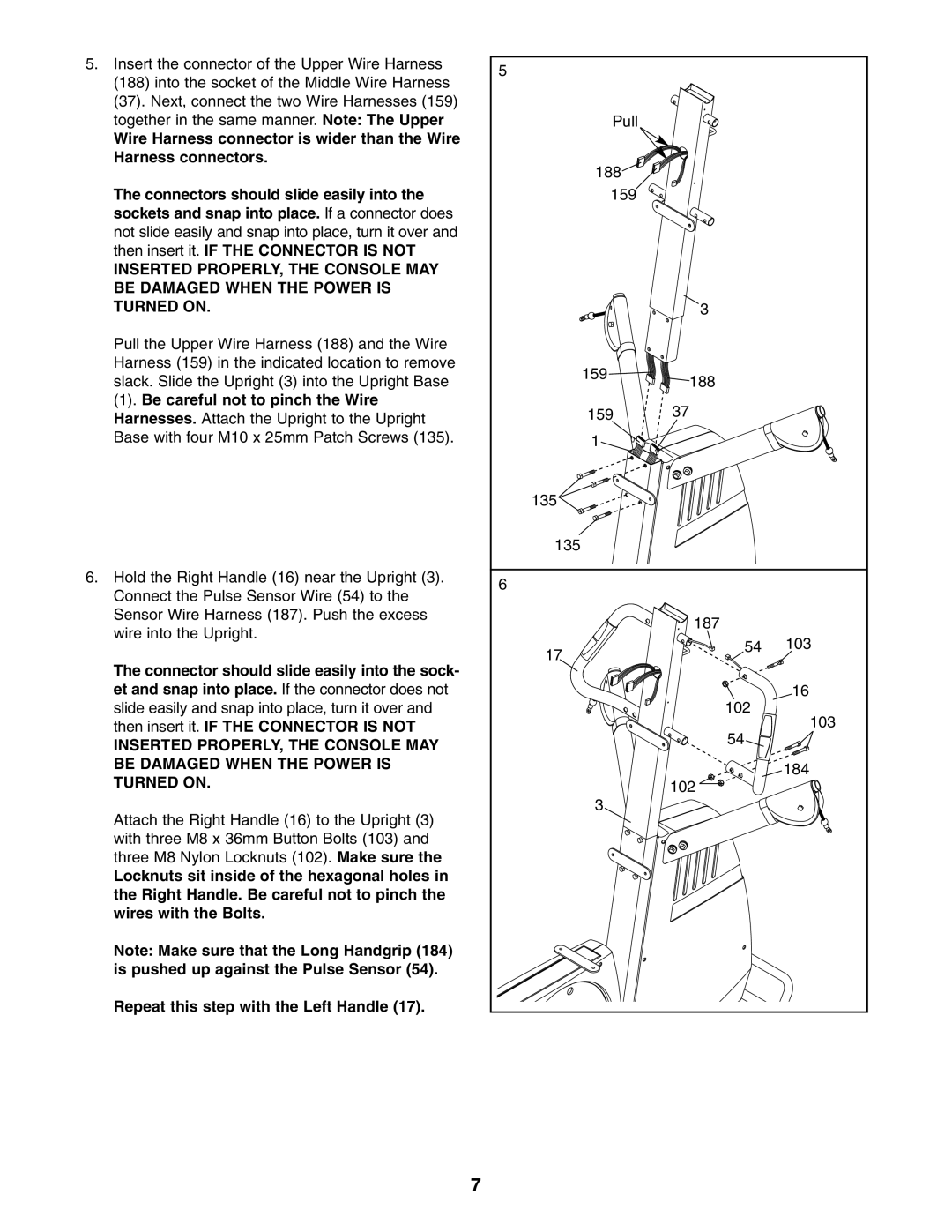
5.Insert the connector of the Upper Wire Harness
(188)into the socket of the Middle Wire Harness
(37).Next, connect the two Wire Harnesses (159) together in the same manner. Note: The Upper
Wire Harness connector is wider than the Wire Harness connectors.
The connectors should slide easily into the sockets and snap into place. If a connector does not slide easily and snap into place, turn it over and then insert it. IF THE CONNECTOR IS NOT
INSERTED PROPERLY, THE CONSOLE MAY BE DAMAGED WHEN THE POWER IS TURNED ON.
Pull the Upper Wire Harness (188) and the Wire Harness (159) in the indicated location to remove slack. Slide the Upright (3) into the Upright Base
(1). Be careful not to pinch the Wire
Harnesses. Attach the Upright to the Upright Base with four M10 x 25mm Patch Screws (135).
6.Hold the Right Handle (16) near the Upright (3). Connect the Pulse Sensor Wire (54) to the Sensor Wire Harness (187). Push the excess wire into the Upright.
The connector should slide easily into the sock- et and snap into place. If the connector does not slide easily and snap into place, turn it over and then insert it. IF THE CONNECTOR IS NOT
INSERTED PROPERLY, THE CONSOLE MAY BE DAMAGED WHEN THE POWER IS TURNED ON.
Attach the Right Handle (16) to the Upright (3) with three M8 x 36mm Button Bolts (103) and three M8 Nylon Locknuts (102). Make sure the
Locknuts sit inside of the hexagonal holes in the Right Handle. Be careful not to pinch the wires with the Bolts.
Note: Make sure that the Long Handgrip (184) is pushed up against the Pulse Sensor (54).
Repeat this step with the Left Handle (17).
5 |
|
|
Pull |
|
|
188 |
|
|
159 |
|
|
| 3 |
|
159 | 188 |
|
|
| |
159 | 37 |
|
1 |
|
|
135 |
|
|
135 |
|
|
6 |
|
|
| 187 |
|
17 | 54 | 103 |
|
| |
| 102 | 16 |
| 103 | |
| 54 | |
|
| |
| 102 | 184 |
|
| |
3 |
|
|
7
