ASSEMBLY
To hire an authorized service technician to assemble the treadmill, call
Assembly requires the included hex key ![]() and your own Phillips screwdriver
and your own Phillips screwdriver ![]()
![]()
![]() (with a
(with a
shaft at least 6" long) and wire cutters ![]() .
.
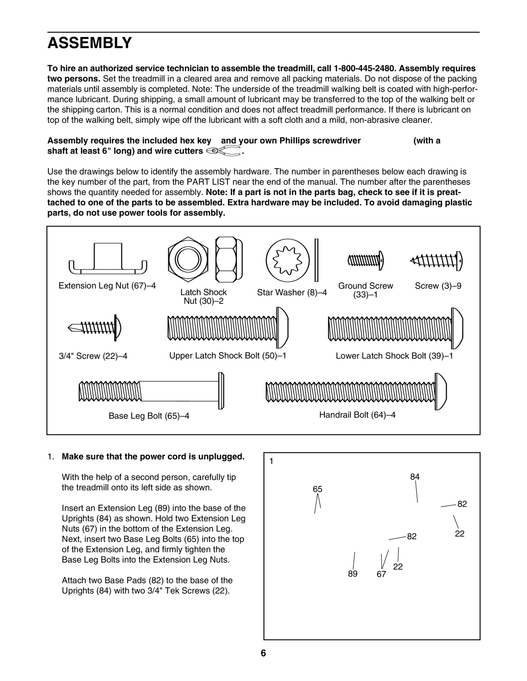
Use the drawings below to identify the assembly hardware. The number in parentheses below each drawing is the key number of the part, from the PART LIST near the end of the manual. The number after the parentheses shows the quantity needed for assembly. Note: If a part is not in the parts bag, check to see if it is preat- tached to one of the parts to be assembled. Extra hardware may be included. To avoid damaging plastic parts, do not use power tools for assembly.
Extension Leg Nut | Latch Shock | Star Washer | Ground Screw | Screw | |
|
| ||||
| Nut |
|
|
|
|
3/4" Screw | Upper Latch Shock Bolt |
| Lower Latch Shock Bolt | ||
Base Leg Bolt |
| Handrail Bolt |
| ||
1. Make sure that the power cord is unplugged. | 1 |
|
|
|
|
| |
With the help of a second person, carefully tip |
| 84 |
|
the treadmill onto its left side as shown. | 65 |
|
|
Insert an Extension Leg (89) into the base of the |
|
| 82 |
|
|
| |
Uprights (84) as shown. Hold two Extension Leg |
|
|
|
Nuts (67) in the bottom of the Extension Leg. |
| 82 | 22 |
Next, insert two Base Leg Bolts (65) into the top |
| ||
|
| ||
|
|
| |
of the Extension Leg, and firmly tighten the |
|
|
|
Base Leg Bolts into the Extension Leg Nuts. |
| 22 |
|
| 89 |
| |
Attach two Base Pads (82) to the base of the | 67 |
| |
|
|
| |
Uprights (84) with two 3/4" Tek Screws (22). |
|
|
|
| 6 |
|
|