QSTD2400 Series DVR User’s Manual
2.3Rear Panel
2.3.1Rear Panel Layout
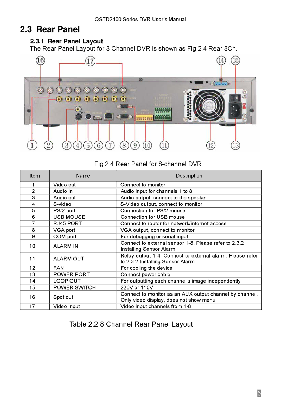
The Rear Panel Layout for 8 Channel DVR is shown as Fig 2.4 Rear 8Ch.
|
|
| Fig 2.4 Rear Panel for | ||
Item |
|
| Name |
| Description |
|
|
|
|
|
|
1 |
| Video out | Connect to monitor | ||
2 |
|
| Audio in |
| Audio input for channels 1 to 8 |
3 |
|
| Audio out | Audio output, connect to the speaker | |
4 |
|
| |||
5 |
|
| PS/2 port |
| Connection for PS/2 mouse |
6 |
|
| USB MOUSE |
| Connection for USB mouse |
7 |
|
| RJ45 PORT |
| Connect to router for network/internet access |
8 |
|
| VGA port | VGA output, connect to monitor | |
9 |
| COM port |
| For debugging or serial input | |
10 |
|
| ALARM IN |
| Connect to external sensor |
|
|
| Installing Sensor Alarm | ||
|
|
|
|
| |
11 |
|
| ALARM OUT |
| Relay output |
|
|
| to 2.3.2 Installing Sensor Alarm | ||
|
|
|
|
| |
12 |
|
| FAN |
| For cooling the device |
13 |
|
| POWER PORT |
| Connect power cable |
14 |
|
| LOOP OUT | For outputting each channel’s image independently | |
15 |
|
| POWER SWITCH |
| 220V or 110V |
16 |
| Spot out |
| Connect to monitor as an AUX output channel by channel. | |
|
| Only video display, does not show menu | |||
|
|
|
|
| |
17 |
| Video input | Video input channels from | ||