Connections: AC Power and Fuses, Master/Sync Output and Slave/Sync Input
AC POWER: | • | The detachable AC power cord connects to the RAVE at the |
| • | There is no power switch; the AC disconnect device is the detachable power cord. |
| • A RAVE operates on line voltages from 100 to 240 VAC, 50 to 60 Hz. No user setting is required. | |
FUSES: | • | The fuse holder is an integral part of the IEC connector and contains two fuses. |
| • To replace a fuse, first detach the AC power cord from the RAVE unit. | |
| • Then use a | |
|
| Replace only with the same type fuse. |
|
| Use only a power source with a protective earth |
|
| ground. |
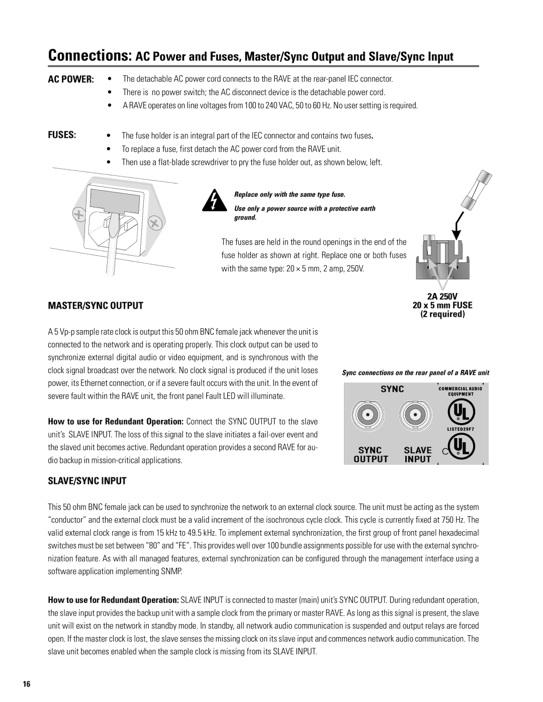
The fuses are held in the round openings in the end of the fuse holder as shown at right. Replace one or both fuses with the same type: 20 × 5 mm, 2 amp, 250V.
2A 250V
MASTER/SYNC OUTPUT20 x 5 mm FUSE (2 required)
A 5
How to use for Redundant Operation: Connect the SYNC OUTPUT to the slave unit’s SLAVE INPUT. The loss of this signal to the slave initiates a
Sync connections on the rear panel of a RAVE unit
SLAVE/SYNC INPUT
This 50 ohm BNC female jack can be used to synchronize the network to an external clock source. The unit must be acting as the system “conductor” and the external clock must be a valid increment of the isochronous cycle clock. This cycle is currently fixed at 750 Hz. The valid external clock range is from 15 kHz to 49.5 kHz. To implement external synchronization, the first group of front panel hexadecimal switches must be set between “80” and “FE”. This provides well over 100 bundle assignments possible for use with the external synchro- nization feature. As with all managed features, external synchronization can be configured through the management interface using a software application implementing SNMP.
How to use for Redundant Operation: SLAVE INPUT is connected to master (main) unit’s SYNC OUTPUT. During redundant operation, the slave input provides the backup unit with a sample clock from the primary or master RAVE. As long as this signal is present, the slave unit will exist on the network in standby mode. In standby, all network audio communication is suspended and output relays are forced open. If the master clock is lost, the slave senses the missing clock on its slave input and commences network audio communication. The slave unit becomes enabled when the sample clock is missing from its SLAVE INPUT.
16