Introduction: Channel Routing
Channel Routing
A RAVE network handles routing in bundles of up to eight audio channels. Each bundle of audio transmitted on the network oc- cupies a unique identifier, or number. In
Similarly, a RAVE 80, with eight AES3 digital outputs, supports network reception of two bundles (each AES3 output carries two audio channels). With receivers, each bundle number need not be unique. A receiver may
signments may be the same. Whether the bundle assignments on a receiver (or multiple receivers) can be duplicated is depen- dent on whether the particular transmitters are setup for unicast or multicast transmission. On network repeaters, all bundles are multicast. On network switches, the value of the bundle assignment determines the addressing of the transmission.
A RAVE device that both sends and receives, such as the RAVE 188 (eight analog inputs and 8 analog outputs) or RAVE 88 (4 AES3 inputs and 4 AES3 outputs), transmits one bundle and can receive another. Note: in software mode, the RAVE 88 and 188 can support two bundles in each direction.
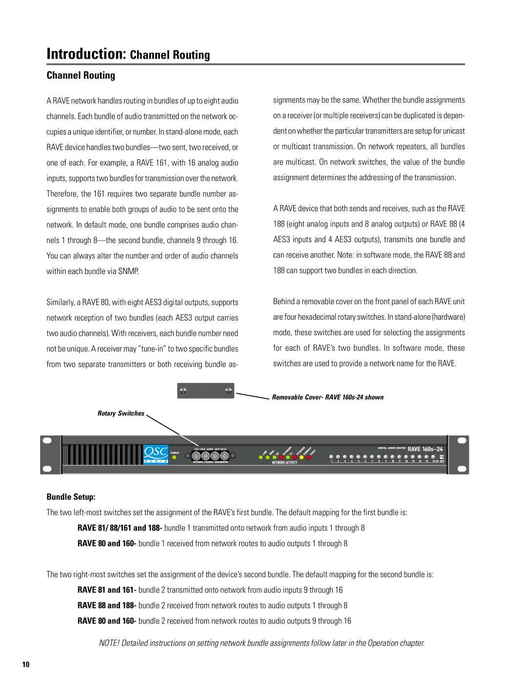
Behind a removable cover on the front panel of each RAVE unit are four hexadecimal rotary switches. In
![]()
![]() Removable Cover- RAVE
Removable Cover- RAVE
Rotary Switches
Bundle Setup:
The two
RAVE 80 and 160- bundle 1 received from network routes to audio outputs 1 through 8
The two
RAVE 88 and 188- bundle 2 received from network routes to audio outputs 1 through 8
RAVE 80 and 160- bundle 2 received from network routes to audio outputs 9 through 16
NOTE! Detailed instructions on setting network bundle assignments follow later in the Operation chapter.
10