Appendix
ETHERNET CABLING
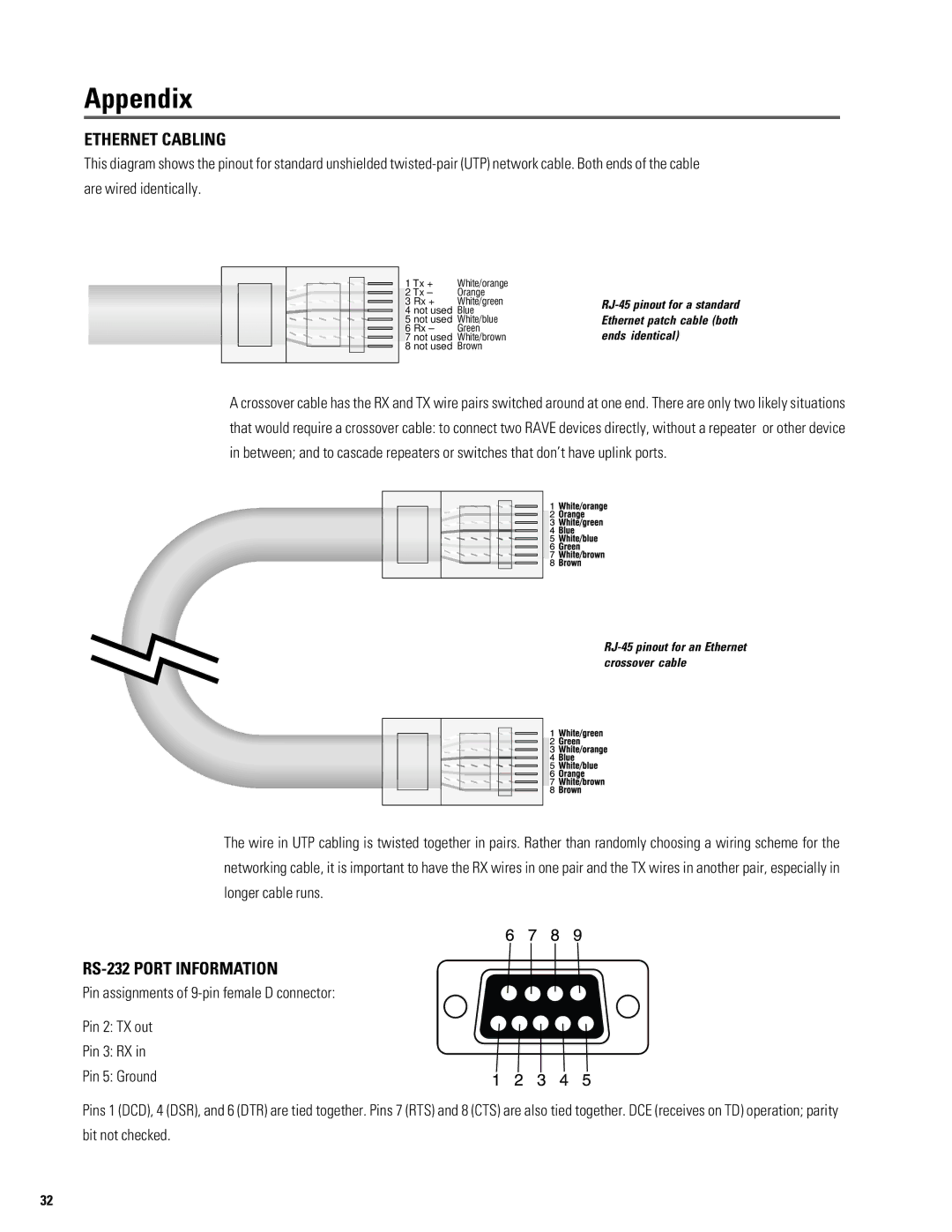
This diagram shows the pinout for standard unshielded
1 Tx + | White/orange |
2 Tx – | Orange |
3 Rx + | White/green |
4 not used | Blue |
5 not used | White/blue |
6 Rx – | Green |
7 not used | White/brown |
8 not used | Brown |
A crossover cable has the RX and TX wire pairs switched around at one end. There are only two likely situations that would require a crossover cable: to connect two RAVE devices directly, without a repeater or other device in between; and to cascade repeaters or switches that don’t have uplink ports.
The wire in UTP cabling is twisted together in pairs. Rather than randomly choosing a wiring scheme for the networking cable, it is important to have the RX wires in one pair and the TX wires in another pair, especially in longer cable runs.
RS-232 PORT INFORMATION
Pin assignments of
Pin 2: TX out
Pin 3: RX in
Pin 5: Ground
Pins 1 (DCD), 4 (DSR), and 6 (DTR) are tied together. Pins 7 (RTS) and 8 (CTS) are also tied together. DCE (receives on TD) operation; parity bit not checked.
32