Operation: Program/Software Kill, Routing
PROGRAM AND “SOFTWARE KILL”
When all front panel hexadecimal switches are set to “FFFF”, the RAVE unit enters a utility mode. This mode can be useful when reprogramming a RAVE or in disabling the software mode of operation.
Reprogramming through the
Since a RAVE may be configured via SNMP and retain its parameter settings, it is possible that a unit may arrive at an installation site where no method of interacting with the device through the software interface is possible. If a unit arrives in this “write” mode, the front panel hexadecimal switches will only affect the device I.D. No bundle or configuration setup is possible through the switch interface in this mode. Setting all front panel hexadecimal switches to “FFFF” and resetting (power cycling) the unit will provide a type of “software kill”. The front panel switches can then be set to the desired bundle assignments and a second device reset will again implement hardware control.
ROUTING
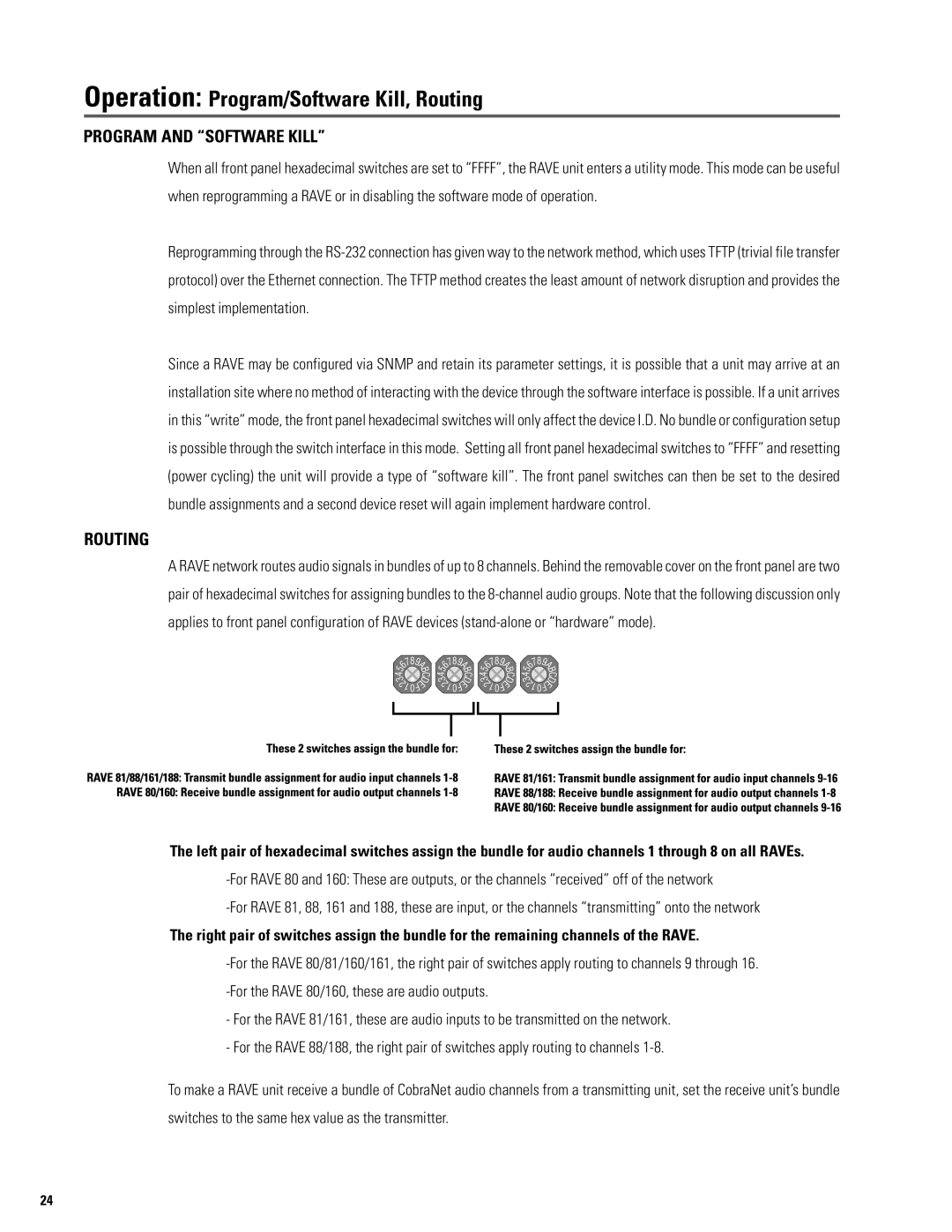
A RAVE network routes audio signals in bundles of up to 8 channels. Behind the removable cover on the front panel are two pair of hexadecimal switches for assigning bundles to the
The left pair of hexadecimal switches assign the bundle for audio channels 1 through 8 on all RAVEs.
The right pair of switches assign the bundle for the remaining channels of the RAVE.
-For the RAVE 81/161, these are audio inputs to be transmitted on the network.
-For the RAVE 88/188, the right pair of switches apply routing to channels
To make a RAVE unit receive a bundle of CobraNet audio channels from a transmitting unit, set the receive unit’s bundle switches to the same hex value as the transmitter.
24