F. Horizontal Termination
Type A - Up & Out Installations for Top Vent Configurations
90º ELBOW center line
PIPE LENGTH | TERMINATION CAP |
|
|
WALL THIMBLE
WALL THIMBLE COVER
![]()
![]() PIPE LENGTH
PIPE LENGTH
Type B - Rear Installations for Use with Rear Vent Kit
CENTER LINE
| |
(451mm) | TERMINATION CAP |
WALL THIMBLE
WALL THIMBLE COVER
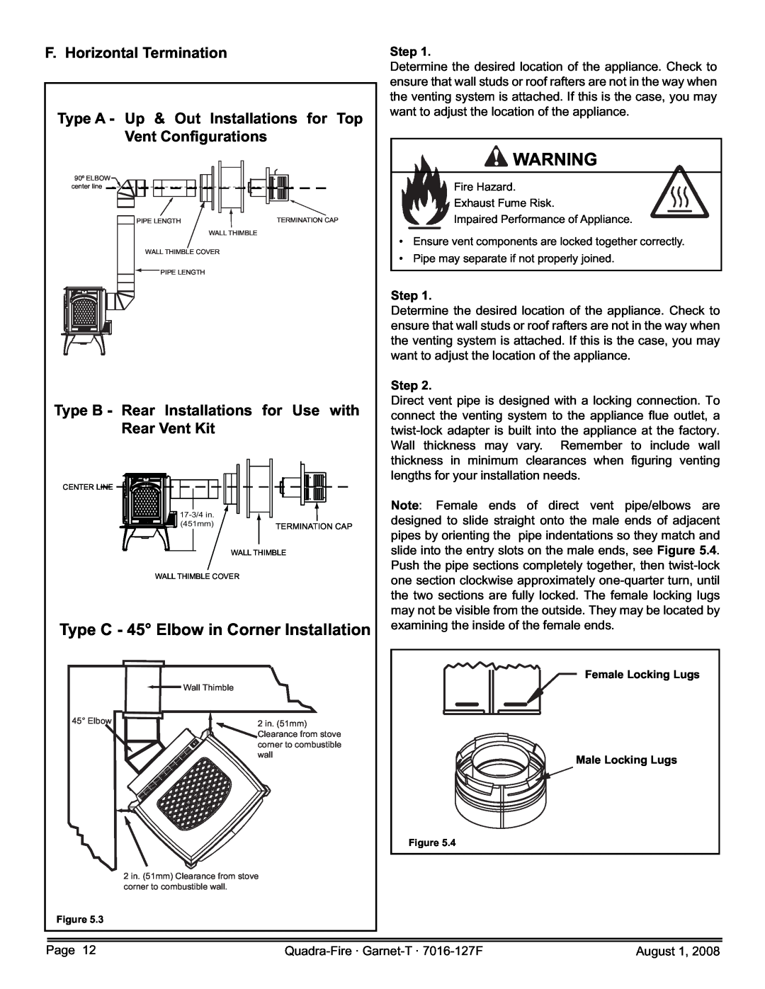
Type C - 45° Elbow in Corner Installation
| Wall Thimble |
45° Elbow | 2 in. (51mm) |
| Clearance from stove |
| corner to combustible |
| wall |
2 in. (51mm) Clearance from stove corner to combustible wall.
Figure 5.3
Step 1.
Determine the desired location of the appliance. Check to ensure that wall studs or roof rafters are not in the way when the venting system is attached. If this is the case, you may want to adjust the location of the appliance.
![]() WARNING
WARNING
Fire Hazard.
Exhaust Fume Risk.
Impaired Performance of Appliance.
•Ensure vent components are locked together correctly.
•Pipe may separate if not properly joined.
Step 1.
Determine the desired location of the appliance. Check to ensure that wall studs or roof rafters are not in the way when the venting system is attached. If this is the case, you may want to adjust the location of the appliance.
Step 2.
Direct vent pipe is designed with a locking connection. To connect the venting system to the appliance flue outlet, a
Note: Female ends of direct vent pipe/elbows are designed to slide straight onto the male ends of adjacent pipes by orienting the pipe indentations so they match and slide into the entry slots on the male ends, see Figure 5.4. Push the pipe sections completely together, then
Female Locking Lugs
Male Locking Lugs
Figure 5.4
Page 12 | August 1, 2008 |