Manuals
/
Quadra-Fire
/
Household Appliance
/
Indoor Fireplace
Quadra-Fire
QV-PIER Fan Wiring Diagram, Optional Accessories, Fan Installation, Wall Switch
Models:
QV-ST
QV-PIER
1
32
41
41
Download
41 pages
18.24 Kb
29
30
31
32
33
34
35
36
Troubleshooting
Install
NG, LP Exploded Parts Diagram
Wiring the Fireplace
Warranty
Maintenance
Symptom
Accessories
Log Assembly
Safety
Page 32
Image 32
Page 31
Page 33
Page 32
Image 32
Page 31
Page 33
Contents
Models QV-Pier QV-ST Series HV-IPI
What to do if you smell gas
Safety and Warning Information
PROHIBITED
Table of Contents
6 Log Assembly
Service Parts List
QV-Pier-HV-IPI
ACCESSORIES
QV-PIER-HV-IPI
COMMON PART
SERIAL #
Service Parts
11710
QV-ST-HV-IPI
NG, LP Exploded Parts Diagram
QV-ST-HV-IPI
QV-ST-HV-IPI
Service Parts
QV-PIER-HV-IPI
1Approvals and Codes
Installation Codes
High Altitude Installations
Appliance Certification
Introducing the Quadra-FireGas Fireplaces
2Getting Started
Pre-installPreparation
Diagram of the QV-PIER-HV-IPI
GAS LINE ACCESS
ELECTRICAL ACCESS
TOP STANDOFFS
REAR VENT
3Installing the Fireplace
Step 1. Locating the Fireplace
Step 2. Framing the Fireplace
Model
QV-PIER-HV-IPI
35-3/4
QV-ST-HV-IPI
NOTE PIPES OVERLAP 1-1/4INCHES AT EACH JOINT
DVP90ST
Step 3. Installing the Vent System
A. Vent System Approvals
TEMS OR COMPONENTS MAY BE USED
Identifying Vent Components
Flue Restrictor Instructions
Figure 13. Venting with One 90 Elbow
Figure 14. Venting with One 90 Elbow
Figure 15. Venting with Two 90 Elbows
Venting with Two 90 Elbows
Figure 17. Venting with Two 90 Elbows
Figure 18. Venting with three 90 elbows
Figure 19. Venting with three 90 elbows
B. Installing Vent Components
Venting Out Vertically
2. Continue Adding Vent Components
Figure 25 Hole & New Framing Members
= AREA WHERE TERMINAL IS NOT PERMITTED
Figure 29. Vent Termination Minimum Clearances
= VENT TERMINAL
X = AIR SUPPLY INLET
Mark the roof hole accordingly
Step 5. The Gas Control System
Pressure
Natural Gas
Propane
5.0 inches
Step 8. Wiring the Fireplace
For Intermittent Pilot Ignition Wiring
Operation using Battery Power
Appliance Requirements
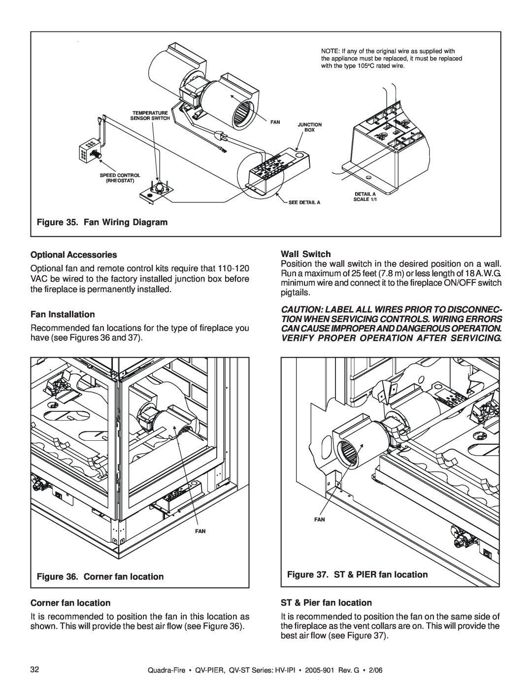
Figure 35. Fan Wiring Diagram
Optional Accessories
Fan Installation
Wall Switch
Figure 40. Sealant Material Hearth Extensions
Step 9. Finishing
IN ANY MANNER
ANDIRON TABS
1/2”
ANDIRONS
Page
Figure 53. Placement of the Ember Material
Placing the Ember Material
Step 12. Lighting the Fireplace
After the Installation
Step 11. Before Lighting the Fireplace
4Maintaining and Servicing Your Fireplace
Fireplace Maintenance
5 Troubleshooting
Symptom
Possible Causes
Corrective Actions
Symptom
Intellifire Ignition System - continued
Possible Causes
Corrective Actions
Lifetime Warranty
LIMITED LIFETIME WARRANTY
THREE YEAR WARRANTY
TWO YEAR WARRANTY
Top
Page
Image
Contents