Step 6. The Gas Supply Line
NOTE: Have the gas supply line installed in accordance with local building codes by a qualified installer approved and/or licensed as required by the locality. (In the Commonwealth of Massachusetts installation must be performed by a licensed plumber or gas fitter).
NOTE: Before the first firing of the fireplace, the gas supply line should be purged of any trapped air.
NOTE: Consult local building codes to properly size the gas supply line leading to the 1/2 inch (13 mm)
This gas fireplace is designed to accept a 1/2 inch (13 mm) gas supply line.
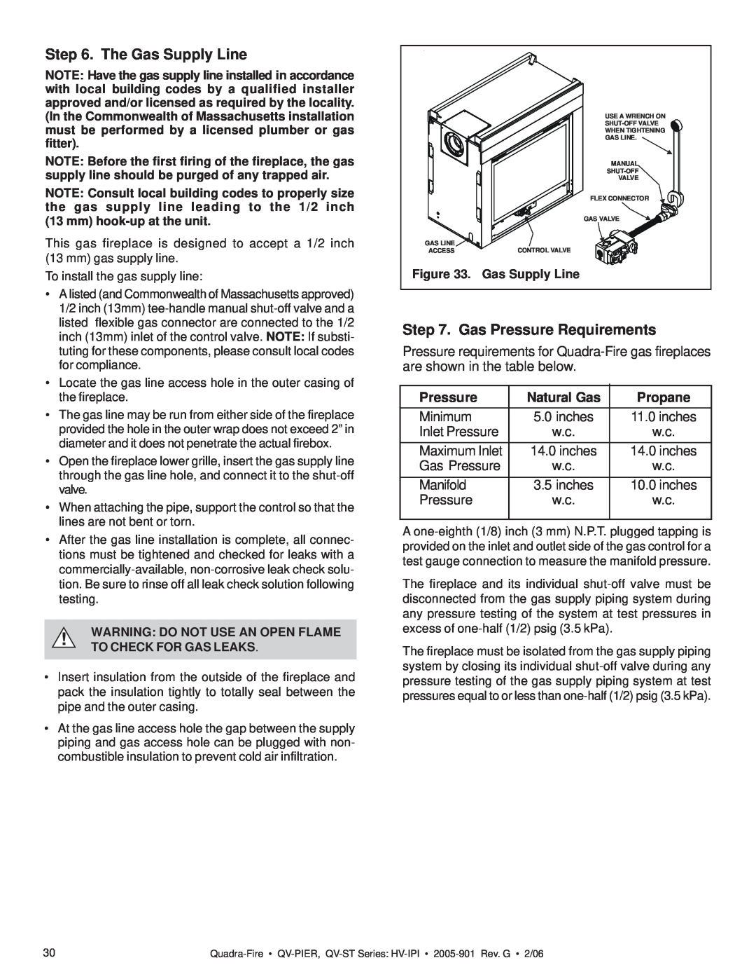
GAS LINE ![]() ACCESS
ACCESS
USE A WRENCH ON
WHEN TIGHTENING
GAS LINE.
MANUAL
VALVE
FLEX CONNECTOR
GAS VALVE ![]()
CONTROL VALVE
To install the gas supply line:
•A listed (and Commonwealth of Massachusetts approved) 1/2 inch (13mm)
•Locate the gas line access hole in the outer casing of the fireplace.
•The gas line may be run from either side of the fireplace provided the hole in the outer wrap does not exceed 2” in diameter and it does not penetrate the actual firebox.
•Open the fireplace lower grille, insert the gas supply line through the gas line hole, and connect it to the
•When attaching the pipe, support the control so that the lines are not bent or torn.
•After the gas line installation is complete, all connec- tions must be tightened and checked for leaks with a
!WARNING: DO NOT USE AN OPEN FLAME TO CHECK FOR GAS LEAKS.
•Insert insulation from the outside of the fireplace and pack the insulation tightly to totally seal between the pipe and the outer casing.
•At the gas line access hole the gap between the supply piping and gas access hole can be plugged with non- combustible insulation to prevent cold air infiltration.
Figure 33. Gas Supply Line
Step 7. Gas Pressure Requirements
Pressure requirements for
Pressure | Natural Gas | Propane |
Minimum | 5.0 inches | 11.0 inches |
Inlet Pressure | w.c. | w.c. |
Maximum Inlet | 14.0 inches | 14.0 inches |
Gas Pressure | w.c. | w.c. |
Manifold | 3.5 inches | 10.0 inches |
Pressure | w.c. | w.c. |
|
|
|
A
The fireplace and its individual
The fireplace must be isolated from the gas supply piping system by closing its individual
30 |