Step 2. Positioning, Leveling, and
Securing the Insert
Remote Control
The receiver for the remotes must be installed BETWEEN the base pan of the insert and the firebox of the
EXISTING SIDE
REFRACTORY
REMOTE
RECEIVER
UNIT
EXISTING BOTTOM
OFFIREPLACE
•Place the insert into position.
•Level the insert from side to side and from front to back. Use the leveling legs if necessary to set each corner of the base. The levelling legs are mounted behind the fan cover plate. For location of fan cover plate, see Figure 11 on page 17.
Step 3. The Gas Control System
!WARNING: THIS UNIT IS NOT FOR USE WITH SOLID FUEL.
These models use a standing pilot ignition type of gas con- trol system.
Standing Pilot Ignition System
This system includes millivolt control valve, standing pilot, thermopile/thermocouple flame sensor, and piezo ignitor.
WARNING:
!CONNECTED TO A CONTROL VALVE IN A MILLIVOLT SYSTEM.
STANDING PILOT
Figure 6. Gas Controls System
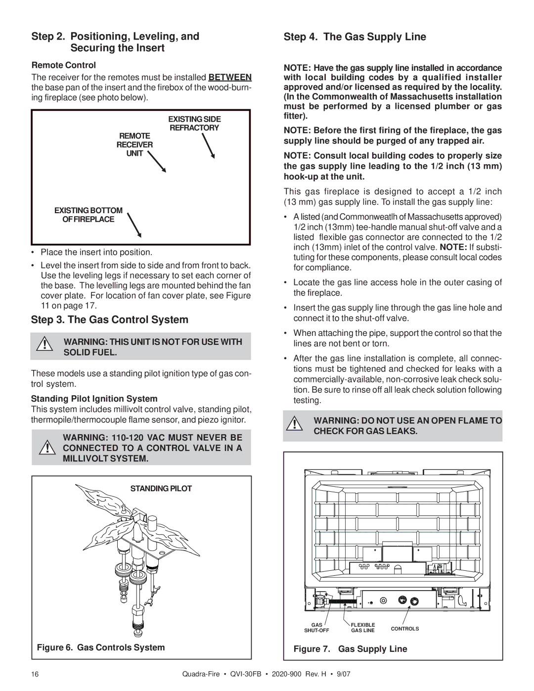
Step 4. The Gas Supply Line
NOTE: Have the gas supply line installed in accordance with local building codes by a qualified installer approved and/or licensed as required by the locality. (In the Commonwealth of Massachusetts installation must be performed by a licensed plumber or gas fitter).
NOTE: Before the first firing of the fireplace, the gas supply line should be purged of any trapped air.
NOTE: Consult local building codes to properly size the gas supply line leading to the 1/2 inch (13 mm)
This gas fireplace is designed to accept a 1/2 inch
(13 mm) gas supply line. To install the gas supply line:
•A listed (and Commonweatlh of Massachusetts approved) 1/2 inch (13mm)
•Locate the gas line access hole in the outer casing of the fireplace.
•Insert the gas supply line through the gas line hole and connect it to the
•When attaching the pipe, support the control so that the lines are not bent or torn.
•After the gas line installation is complete, all connec- tions must be tightened and checked for leaks with a
!WARNING: DO NOT USE AN OPEN FLAME TO CHECK FOR GAS LEAKS.
GAS | FLEXIBLE | CONTROLS | |
GAS LINE | |||
| |||
Figure 7. Gas Supply Line | |||
16 |