Step 5. Gas Pressure Requirements
Pressure requirements for these gas appliances are shown in the table below.
Pressure | Natural Gas | Propane |
Minimum | 5.0 inches | 11.0 inches |
Inlet Pressure | w.c. | w.c. |
Maximum Inlet | 14.0 inches | 14.0 inches |
Gas Pressure | w.c. | w.c. |
Manifold | 3.5 inches | 10.0 inches |
Pressure | w.c. | w.c. |
Inlet and outlet pressure taps are provided on the front face of the gas control for a test gauge connection to measure the manifold pressure. Use a small flat blade screwdriver to crack open the screw in the center of the tap. Position a rubber hose over the tap to obtain the pressure reading.
THE FIREPLACE AND ITS INDIVIDUAL
Step 6. Wiring the Fireplace
Use of the electrical junction box provided is required if using a blower or remote. Plug the cord into a convenient outlet. An electrician may install an outlet box inside the fireplace. Place the outlet in the lower, back corner of the fireplace. Make sure fan doesn’t touch back wall. Optional remote controls are available and should be installed along the side of the insert (see Step 2. Positioning, Leveling and securing the Insert).
WARNING: MUST USE THE CORD SUPPLIED
!WITH THE J-BOX.
•This appliance REQUIRES
NOTE: Electrical wiring must be installed by a li- censed electrician.
CAUTION: DISCONNECT REMOTE CONTROLS IF AB- SENT FOR EXTENDED TIME PERIODS. THIS WILL PRE- VENT ACCIDENTAL APPLIANCE OPERATION.
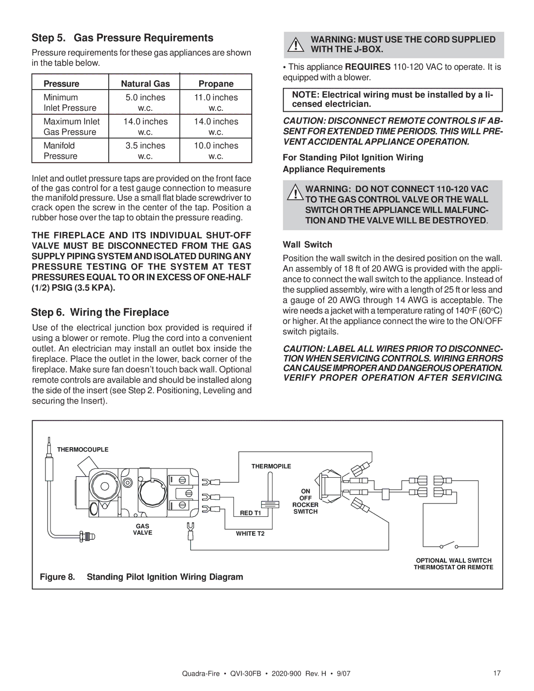
For Standing Pilot Ignition Wiring
Appliance Requirements
!WARNING: DO NOT CONNECT
Wall Switch
Position the wall switch in the desired position on the wall. An assembly of 18 ft of 20 AWG is provided with the appli- ance to connect the wall switch to the appliance. Instead of the supplied assembly, wire with a length of 25 ft or less and a gauge of 20 AWG through 14 AWG is acceptable. The wire needs a jacket with a temperature rating of 140oF (60oC) or higher. At the appliance connect the wire to the ON/OFF switch pigtails.
CAUTION: LABEL ALL WIRES PRIOR TO DISCONNEC- TION WHEN SERVICING CONTROLS. WIRING ERRORS CAN CAUSE IMPROPERAND DANGEROUS OPERATION. VERIFY PROPER OPERATION AFTER SERVICING.
THERMOCOUPLE |
|
| |
|
| THERMOPILE |
|
|
|
| ON |
|
|
| OFF |
|
|
| ROCKER |
|
| RED T1 | SWITCH |
| GAS |
|
|
| VALVE | WHITE T2 |
|
|
|
| OPTIONAL WALL SWITCH |
Figure 8. | Standing Pilot Ignition Wiring Diagram | THERMOSTAT OR REMOTE | |
| |||
17 |