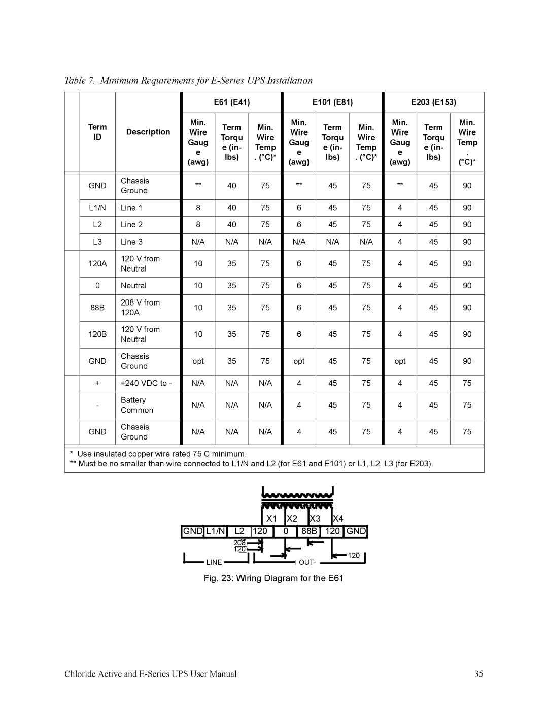
Table 7. Minimum Requirements for E-Series UPS Installation


E61 (E41)


E101 (E81)


E203 (E153)


Term

Description

Min.


Term


Min.


Min.


Term


Min.

Min.


Term


Min.


Wire


Wire


Wire


Wire


ID


Torqu


Wire


Torqu


Wire


Torqu


Gaug


Gaug


Gaug


Temp


e (in-


Temp


e (in-


Temp


e (in-


e


e


e


.


lbs)


. (°C)*


lbs)


. (°C)*


lbs)


(awg)


(awg)


(awg)


(°C)*


GND

Chassis

**


40


75


**


45


75

**


45


90


Ground


L1/N

Line 1

8


40


75


6


45


75

4


45


90


L2

Line 2

8


40


75


6


45


75

4


45


90


L3

Line 3

N/A


N/A


N/A


N/A


N/A


N/A

4


45


90


120A

120 V from

10


35


75


6


45


75

4


45


90


Neutral


0

Neutral

10


35


75


6


45


75

4


45


90


88B

208 V from

10


35


75


6


45


75

4


45


90


120A


120B

120 V from

10


35


75


6


45


75

4


45


90


Neutral


GND

Chassis

opt


35


75


opt


45


75

opt


45


90


Ground


+

+240 VDC to -

N/A


N/A


N/A

4


45


75

4


45


75


-

Battery

N/A


N/A


N/A

4


45


75

4


45


75


Common


GND

Chassis

N/A


N/A


N/A

4


45


75

4


45


75


Ground


* Use insulated copper wire rated 75 C minimum.


** Must be no smaller than wire connected to L1/N and L2 (for E61 and E101) or L1, L2, L3 (for E203).


X1

X2

X3

X4


GND L1/N

L2

120

0

88B

120

GND


208


120


120

LINE


OUT-


Fig. 23: Wiring Diagram for the E61

Chloride Active and E-Series UPS User Manual

35

Page 39
Image 39
Rackmount Solutions VA 6000, VA 3000, VA 700, VA 10000, VA 2000 Minimum Requirements for E-Series UPS Installation, Lbs Awg

VA 2000, VA 10000, VA 700, VA 3000, VA 20000 specifications

Rackmount Solutions offers a versatile lineup of VA series products designed for efficient power management in data centers and server environments. The VA 1000, VA 6000, VA 20000, VA 3000, and VA 700 models cater to a variety of power needs, ensuring reliable performance and robust features tailored to different operational demands.

Starting with the VA 1000, this model is compact yet powerful, providing up to 1000VA of power capacity. It features an LCD display that offers real-time information on power status, battery life, and load levels. The VA 1000 is equipped with pure sine wave output, ensuring compatibility with sensitive electronic equipment and providing protection against power surges. The unit is designed for easy integration into existing IT frameworks, with multiple outlets to accommodate various devices.

Next in the lineup, the VA 3000 model steps up the capacity to 3000VA. This unit excels in larger environments where higher power demands are common. It too features pure sine wave output and includes advanced battery management technology that optimizes performance and prolongs battery life. Its networking capabilities allow for remote management and monitoring through a web interface, providing IT managers with comprehensive control over their power infrastructure.

The VA 6000 doubles down on capacity, supporting robust applications with its 6000VA rating. It is equipped with advanced features such as surge protection, automatic voltage regulation, and a high-efficiency design that reduces energy consumption. Its modular design allows for ease of maintenance and upgrades, making it a cost-effective solution over time for growing data centers.

For the larger setups, the VA 20000 model stands out with a staggering 20000VA power capacity. Designed for high-demand applications, this unit incorporates features like redundancy and N+1 configurations to ensure uninterrupted power supply. Its scalable architecture makes it suitable for both small and large enterprises looking to future-proof their power infrastructure.

Lastly, the VA 700 model serves as an entry-level solution at 700VA. Ideal for small servers and networking devices, it offers essential features like battery monitoring and basic surge protection, making it a cost-effective choice for small business environments.

In summary, the Rackmount Solutions VA series, comprising models VA 1000, VA 3000, VA 6000, VA 20000, and VA 700, collectively offer a comprehensive suite of power management solutions. Their scalable designs, advanced technologies, and focus on efficiency make them ideal for a wide range of applications, from small offices to large data centers, ensuring reliability and performance in critical environments.