shutting itself down during a power down. They then allow the battery to take over memory retention of the data in the microcontroller.
Now here comes the fun! Take your time on the next stages as they can make or break your kit. Don't be a bozo and rush assembly to get it done, hook it up, and then destroy it. Play it smart and have patience and your kit will make you proud when it works the first time!
Locate the display board and orient it in the same direction in the parts layout diagram.
36. Install DSP1, one of the seven segment displays. Pay very close attention to where the decimal point is in reference to the notches on the board. Notice the decimal point faces the lower right of the board. This is where the soldering becomes difficult, the pads are very close to the traces, and solder bridges are easier to make. A small tipped soldering iron with a clean tip (wipe it often on a damp sponge) is required for best results. This is where patience really counts! Check and double check orientation before soldering, since desoldering on these fine traces will absolutely destroy them.
37. Hope you had a fun time doing the first display, now you get to do it five more times! Install DSP2 - DSP6 using the same technique as above. Start with DSP2 and in order end with DSP6. This prevents finger squeezing and much ranting and raving.
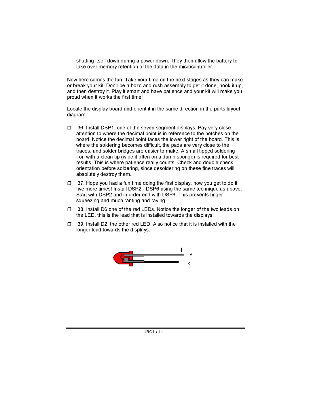
38. Install D6 one of the red LEDs. Notice the longer of the two leads on the LED, this is the lead that is installed towards the displays.
39. Install D2, the other red LED. Also notice that it is installed with the longer lead towards the displays.
A
K
