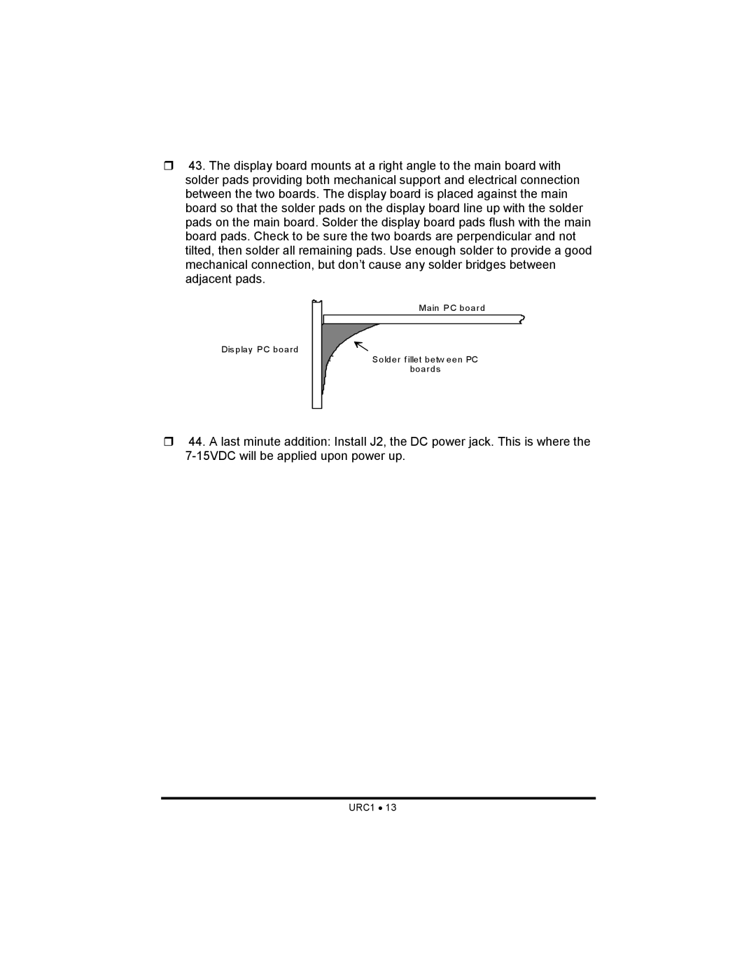
43. The display board mounts at a right angle to the main board with solder pads providing both mechanical support and electrical connection between the two boards. The display board is placed against the main board so that the solder pads on the display board line up with the solder pads on the main board. Solder the display board pads flush with the main board pads. Check to be sure the two boards are perpendicular and not tilted, then solder all remaining pads. Use enough solder to provide a good mechanical connection, but don’t cause any solder bridges between adjacent pads.
Main PC board
Dis play PC board
Solder f illet betw een PC
boards
44. A last minute addition: Install J2, the DC power jack. This is where the