Locate the main board again and we will finish it up.
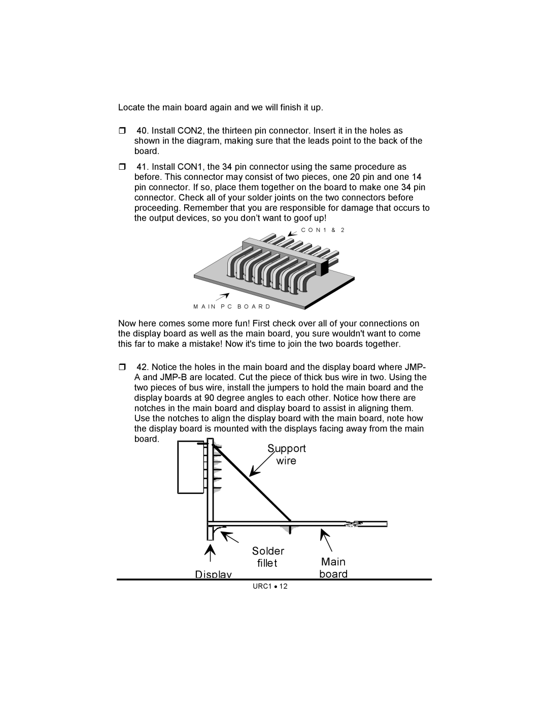
40. Install CON2, the thirteen pin connector. Insert it in the holes as shown in the diagram, making sure that the leads point to the back of the board.
41. Install CON1, the 34 pin connector using the same procedure as before. This connector may consist of two pieces, one 20 pin and one 14 pin connector. If so, place them together on the board to make one 34 pin connector. Check all of your solder joints on the two connectors before proceeding. Remember that you are responsible for damage that occurs to the output devices, so you don’t want to goof up!
C O N 1 & 2
M A I N P C B O A R D
Now here comes some more fun! First check over all of your connections on the display board as well as the main board, you sure wouldn't want to come this far to make a mistake! Now it's time to join the two boards together.
42. Notice the holes in the main board and the display board where JMP- A and
the display board is mounted with the displays facing away from the main board.