90 Ceramic specifications
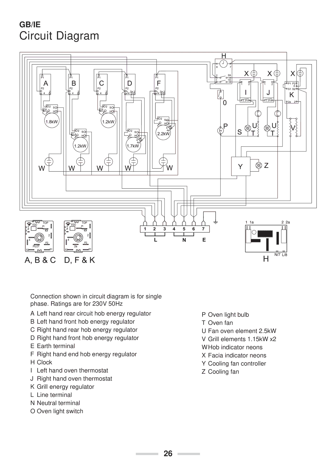
The Rangemaster 90 Ceramic is an exceptional range cooker that embodies both style and functionality, making it a desirable addition to any modern kitchen. With a classic design that complements various kitchen aesthetics, the Rangemaster 90 Ceramic offers a blend of traditional craftsmanship and contemporary technology that meets the needs of today’s home chef.One of the standout features of the Rangemaster 90 Ceramic is its dual fuel cooking system, which combines the precision of gas cooking with the even heat distribution of an electric oven. The gas hob offers multiple burners, enabling efficient cooking of multiple dishes at once. Its powerful wok burner is particularly impressive, providing a high heat for stir-frying while the more moderate burners are ideal for simmering sauces or boiling pasta.
The oven compartment is where the Rangemaster 90 Ceramic truly shines. With two spacious electric ovens, chefs can cook a variety of dishes simultaneously, utilizing the different functions available. The multifunction oven means you can choose from various cooking modes, such as conventional baking, fan-assisted cooking, or grilling, allowing for maximum versatility. The inclusion of a programmable timer helps to monitor cooking times, ensuring your dishes are cooked to perfection.
Additionally, the Rangemaster 90 features an integrated grill with adjustable settings, which adds further flexibility to your cooking options. The ceramic interior is not only stylish but also practical, as it aids in heat retention and cleaning. The smooth surface minimizes the risk of food sticking, enhancing the ease of maintenance.
In terms of user-friendly characteristics, the Rangemaster 90 Ceramic comes with sturdy, ergonomic control knobs that provide precise temperature control. The LED display and innovative touch controls add to its modern appeal, ensuring that adjustments can be made with ease.
Safety is also a priority with the Rangemaster 90 Ceramic. It features an automatic ignition system, ensuring quick and safe start-ups without the need for matches or lighters. The built-in flame failure device adds an extra layer of safety by cutting off gas flow if the flame goes out.
In summary, the Rangemaster 90 Ceramic is a sophisticated range cooker that combines advanced cooking technologies with timeless design. Its versatile cooking modes, spacious oven compartments, and modern safety features make it a valuable asset for both amateur cooks and seasoned chefs alike. Whether you're preparing a family meal or entertaining guests, the Rangemaster 90 Ceramic is sure to elevate your culinary experience.

